Hi,
This is a tough one because it must be stuck in the duct. The only way I know to remove the defroster duct requires removal of the heater/AC unit which is a big job. Once it is out, then you can take things apart. I can provide all the directions, but it is really involved. However, I would be happy to do it.
Tell me, when you had the blower motor out, did you try switching between air flow modes? For example, switching between defroster, floor, and panel settings?
Also, I'm not sure what type of ring it was. If it is gold, a magnet won't work (actually can repel it). If it is something which is a magnet can attract? If so, they make small mechanic magnets which bend. You may be able to attract it that way.
___________________________
Okay, I am going to provide the directions for removal of the unit. This is involved, but I'm adding it if you need to go this far. All attached pics correlate with the directions.
___________________________
2017 Hyundai Truck Tucson FWD L4-2.0L
Heater Unit - Repair Procedures
Vehicle Heating and Air Conditioning Housing Assembly HVAC Service and Repair Procedures Heater Unit - Repair Procedures
HEATER UNIT - REPAIR PROCEDURES
Replacement
When prying with a flat-tip screwdriver or use a prying trim tool, wrap it with protective tape, and apply protective tape around the related parts, to prevent damage.
Disconnect the negative (-) battery terminal.
Recover the refrigerant with a recovery/recycling/charging station.
When the engine is cool, drain the engine coolant from the radiator.
(Refer to Engine Mechanical System - “Coolant”)
Remove the cowl top cover.
(Refer to Body - "Cowl Top Cover")
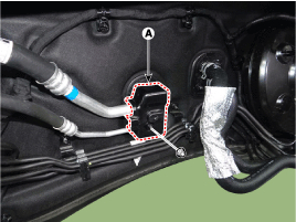
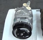
After loosening the mounting nut, remove the expansion valve cover (A).
Tightening torque :
7.8 11.8 N.M ( 0.8 1.2 kgf.M, 5.7 8.7 Ib-ft)
pic 1
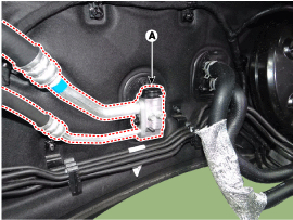
Remove the bolts and the expansion valve (A) from the evaporator core.
Tightening torque :
7.8 11.8 N.M ( 0.8 1.2 kgf.M, 5.7 8.7 Ib-ft)
pic 2
Plug or cap the lines immediately after disconnecting them to avoid moisture and dust contamination.
When installing, replace with a new O-ring.
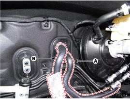
Disconnect the inlet (A) and outlet (B) heater hoses from the heater unit.
Pic 3
Engine coolant will run out when the hoses are disconnected; drain it into a clean drip pan. Be sure not to let coolant spill on electrical parts or painted surfaces. If any coolant spills, rinse it off immediately.
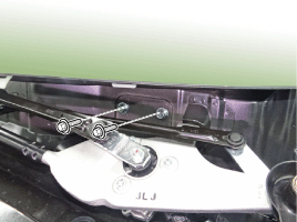
Loosen the cowl cross member mounting bolts.
Pic 4
Remove the floor console assembly.
(Refer to Body - "Floor Console Assembly")
Remove the crash pad lower panel.
(Refer to Body - "Crash Pad Lower Panel")
Remove both sides of the front pillar trim.
(Refer to Body - "Front Pillar Trim")
Remove the cowl side trim.
(Refer to Body - "Cowl Side Trim")
Remove the steering column shroud lower panel.
(Refer to Body - "Steering Column Shroud Panel")
Remove the steering wheel.
(Refer to Steering System - "Steering Wheel")
Remove the multifunction switch.
(Refer to Body Electrical System - "Multifunction Switch")
Lower the steering column after loosening the mounting bolts.
(Refer to Steering System - "Steering Column and Shaft")
Remove the shift lever assembly.
(Refer to Automatic Transmission System - "Shift Lever")
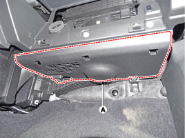
Remove the crash pad under cover [RH].
Pic 5
Remove the accelerator pedal.
(Refer to Engine Control / Fuel System - "Accelerator Position Sensor (APS)")
Separate the floor carpet (A) to obtain space for removing the rear heating duct.
Pic 6
Loosen the mounting nut and remove the rear air duct (A).
Pic 7
Disconnect the airbag control module (SRSCM) connector (A).
Pic 8
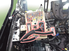
Disconnect the junction box connectors (A).
Pic 9
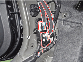
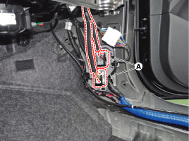
Disconnect the multi box connectors (A).
[Driver''s side]
pic 10
[Passenger''s side]
pic 11
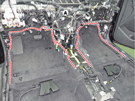
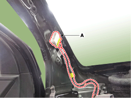
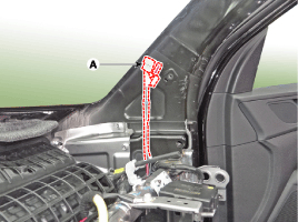
Disconnect the connectors (A) and the mounting clips in the front pillar.
[Driver''s side]
pic 12
[Passenger''s side]
pic 13
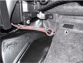
Remove the drain hose (A).
Pic 14
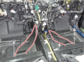
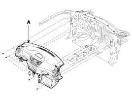
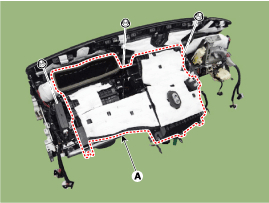
After loosening the bolts and nuts remove the main crash pad and cowl cross bar assembly (A) together.
Pic 15
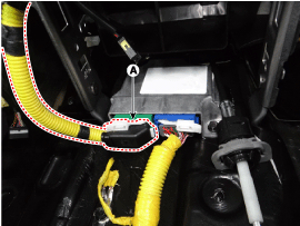
Disconnect the heater & blower unit connectors.
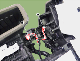
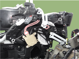
Disconnect the auto defogging actuator connector (A), intake actuator connector (B) and remove the wiring mounting clips.
Pic 16
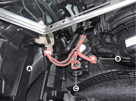
Disconnect the driver''s side temperature control actuator (A), mode control actuator (B) connectors and remove the wiring mounting clips.
Pic 17
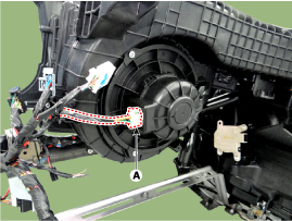
Disconnect the blower motor connector (A) and remove the wiring mounting clips.
Pic 18
Disconnect the passenger''s side temperature control actuator (A), cluster ionizer connector (B), power mosfet connector (C) connectors and then remove the wiring mounting clips.
Pic 19
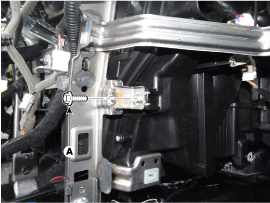
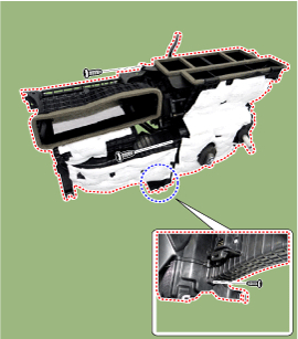
Loosen the heater & blower unit mounting bolt (A).
Pic 20
Remove the heater and blower unit (A) from the crash pad (B) after loosening the mounting nuts.
Pic 21
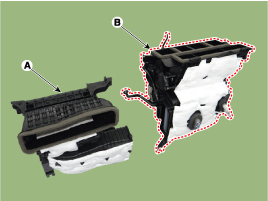
Separate the blower unit (A) from the heater unit (B) after loosening the screws.
Pic 22
pic 23
Install in the reverse order of removal.
_____________________________
Let me know if this helps or if you have other questions.
Joe
Images (Click to make bigger)
SPONSORED LINKS
Wednesday, March 11th, 2020 AT 9:54 PM