Hello -
Thanks for the info.
Sounds like a great car. . .. . .. . ..maybe send us a pic once we have it fixed. . .. . ...
Was the heater working before they worked on it?
Sorry, I want to make sure I understand you , when you say all hoses are hot. . ..both the heater hoses going in and coming out of the firewall are both hot. . ...yes?
The blower works just fine as far as if you select defrost air comes out of the defrost, if you select floor, then floor or vents, good air flow through the vents?
The blower works just fine in all speeds
The AC works just fine in all those same positions?
Does it work any different in Automatic or manual or you still have the same problem
It is odd it doesn't throw a code. . .. . ..I show a code B1249 is for Blend Door Actuator Short or Blend Door Actuator Failure
On your instrument fuse panel just to make sure we are good, please check fuses, 20, 9, and 34 and the in the engine compartment please check 23 and29.
I have attached the testing for the blend door. . .. . ..It sounds like that may be the problem but you figure it would have thrown a code.
TEST D: INSUFFICIENT, ERRATIC OR NO HEAT
1. Check For Proper Engine Coolant Level
Turn ignition off. Check engine coolant level when hot and cold. If engine coolant is at proper level (hot and cold) on coolant reservoir tank, go to next step. If engine coolant level is not at proper level, go to step 3).
2. Check For Hot Water To Heater Core Inlet Hose
Start engine and bring to normal operating temperature. With engine running, feel heater core inlet hose. If heater core inlet hose is too hot to handle, go to step 4). If heater core inlet hose is not too hot to handle, repair cooling system as necessary. Retest system.
3. Check Cooling System (Including Radiator Cap) For Leaks
Fill cooling system to correct level. Pressure check engine cooling system. If engine cooling system (including radiator cap) holds pressure, go to next step. If engine cooling system (including radiator cap) does not hold pressure, repair engine cooling system as necessary. Retest system.
4. Check Heater Core Outlet For Hot Water
Start engine and bring to operating temperature. With engine running, feel heater core outlet hose. If heater core outlet hose is cool or cold, check heater core for plugged condition. Repair as necessary. If heater core outlet hose is not cool or cold, go to DTC B1249 TEST: BLEND DOOR FAILURE .
DTC B1249 TEST: BLEND DOOR FAILURE
1. Check Actuator Clockwise Operation (Full Cool)
Turn ignition off. Disconnect EATC module connectors. Connect jumper wire between EATC connector C272 terminals No. 13 (Brown/Light Green wire) and No. 24 (Red wire). Connect a second jumper wire between EATC connector C272 terminals No. 26 (Purple wire) and No. 11 (Black wire). See Fig. 4 . If blend door actuator motor moves clockwise, go to next step. If blend door actuator motor does not move clockwise, go to step 3).
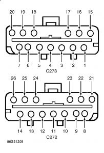
Fig. 4: Identifying Electronic Automatic Temperature Control (EATC) Module Connector Terminals
Courtesy of FORD MOTOR CO.
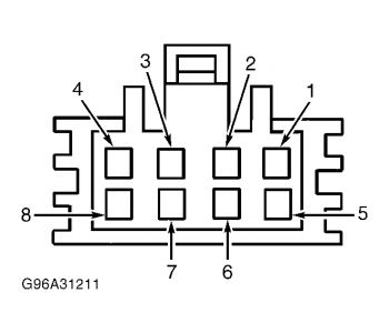
Fig. 5: Identifying Blend Door Actuator Connector Terminals
Courtesy of FORD MOTOR CO.
2. Check Actuator Counterclockwise Operation (Full Hot)
Connect a jumper wire between EATC connector C272 terminals No. 26 (Purple wire) and No. 24 (Red wire). Connect second jumper wire between EATC connector C272 terminals No. 13 (Brown/Light Green wire) and No. 11 (Black wire). See Fig. 4 . If blend door actuator motor moves counterclockwise, go to step 7). If blend door actuator motor does not move counterclockwise, go to next step.
3. Check Purple Wire For Short
Disconnect electronic blend door actuator connector. With an ohmmeter, measure resistance between ground and EATC connector C272 terminal No. 26 (Purple wire). See Fig. 4 . If resistance is greater than 10,000 ohms, go to next step. If resistance is not greater than 10,000 ohms, repair short to ground in Purple wire.
4. Check Brown/Light Green Wire For Short
Measure resistance between ground and EATC connector C272 terminal No. 13 (Brown/Light Green wire). See Fig. 4 . If resistance is greater than 10,000 ohms, go to next step. If resistance is not greater than 10,000 ohms, repair short to ground in Brown/Light Green wire.
5. Check Purple Wire For Open
Measure resistance between EATC connector C272 terminal No. 26 (Purple wire) and blend door actuator connector terminal No. 8 (Purple wire). See Fig. 4 and Fig. 5 . If resistance is less than 5 ohms, go to next step. If resistance is not less than 5 ohms, repair open in Purple wire.
6. Check Brown/Light Green Wire For Open
Measure resistance between EATC connector C272 terminal No. 13 (Brown/Light Green wire) and blend door actuator connector terminal No. 7 (Brown/Light Green wire). See Fig. 4 and Fig. 5 . If resistance is less than 5 ohms, go to next step. If resistance is not less than 5 ohms, repair open in Brown/Light Green wire and retest system.
7. Check Actuator Operation
Remove electronic blend door actuator. See TEMPERATURE BLEND DOOR ACTUATOR in REMOVAL & INSTALLATION. Attach electronic blend door connector. With actuator drive shaft disengaged from temperature blend door, connect jumper wires, as in step 1), and drive electronic blend door full clockwise. Change jumper wire positions, as in step 2), and drive electronic blend door full counterclockwise. If electronic blend door actuator moved fully in both directions, repair temperature blend door for blocked or binding condition and retest system. If door did not move as indicated, replace electronic blend door actuator and retest system.
8. Check Feedback Potentiometer Resistance
Disconnect EATC connector C273. Following instructions in step 2), drive blend door actuator fully counterclockwise. With blend door actuator in fully counterclockwise position, measure resistance between EATC connector terminals No. 17 (Red/Light Green) and No. 4 (Red/White wire). See Fig. 4 . If resistance is 5,000-7,000 ohms, go to step 13). If resistance is not 5,000-7,000 ohms, go to next step.
9. Check Red/Light Green Wire For Open
Disconnect blend door actuator connector. Measure resistance between EATC connector C273 terminal No. 17 (Red/Light Green wire) and blend door actuator connector terminal No. 5 (Red/Light Green wire). See Fig. 4 and Fig. 5 . If resistance is less than 5 ohms, go to next step. If resistance is not less than 5 ohms, repair open in Red/Light Green wire. Retest system.
10. Check Red/White Wire For Open
Measure resistance between EATC connector C273 terminal No. 4 (Red/White wire) and blend door actuator connector terminal No. 6 (Red/White wire). See Fig. 4 and Fig. 5 . If resistance is less than 5 ohms, go to next step. If resistance is not less than 5 ohms, repair open in Red/White wire. Retest system.
11. Check Red/Light Green Wire For Short
Measure resistance between EATC module connector C273 terminal No. 17 (Red/Light Green wire) and ground. If resistance is more than 10,000 ohms, go to next step. If resistance is less than 10,000 ohms, repair short to ground in Red/Light Green wire and retest system.
12. Check Red/White Wire For Short
Measure resistance between EATC module connector C273 terminal No. 4 (Red/White wire) and ground. See Fig. 4 . If resistance is more than 10,000 ohms, replace electronic blend door and retest system. If resistance is less than 10,000 ohms, repair short to ground in Red/White wire and retest system.
13. Check Feedback Potentiometer Low Side Resistance
Following instructions in step 2), drive blend door actuator fully counterclockwise. With blend door actuator in fully counterclockwise position, measure resistance between EATC connector C273 terminals No. 3 (Yellow/Light Green) and No. 4 (Red/White wire). See Fig. 4 . If resistance is 250-1,500 ohms, go to step 16). If resistance is not 250-1,500 ohms, go to next step.
14. Check Yellow/Light Green Wire For Open
Disconnect electronic blend door actuator connector. Measure resistance between EATC connector C273 terminal No. 3 (Yellow/Light Green wire) and blend door actuator connector terminal No. 1 (Yellow/Light Green wire). See Fig. 4 and Fig. 5 . If resistance is less than 5 ohms, go to next step. If resistance is not less than 5 ohms, repair open in Yellow/Light Green wire. Retest system.
15. Check Yellow/Light Green Wire For Short
Measure resistance between EATC module C273 terminal No. 3 (Yellow/Light Green wire) and ground. See Fig. 4 . If resistance is more than 10,000 ohms, replace electronic blend door actuator and retest system. If resistance is less than 10,000 ohms, repair short to ground in Yellow/Light Green wire and retest system.
16. Check Feedback Potentiometer High Side Resistance
Following instructions in step 2), drive blend door actuator fully counterclockwise. With blend door actuator in fully counterclockwise position, measure resistance between EATC connector C273 terminals No. 17 (Red/Light Green) and No. 3 (Yellow/Light Green wire). See Fig. 4 . If resistance is 3,500-6,000 ohms, go to next step. If resistance is not 3,500-6,000 ohms, replace electronic blend door actuator. Retest system.
17. Check Red/Light Green Wire For Short
Measure resistance between EATC connector C273 terminal No. 17 (Red/Light Green wire) and ground. See Fig. 4 . If resistance is greater than 10,000 ohms, go to next step. If resistance is not greater than 10,000 ohms, repair short to ground in Red/Light Green wire. Retest system.
18. Check Red/White Wire For Short
Measure resistance between EATC connector C273 terminal No. 4 (Red/White wire) and ground. See Fig. 4 . If resistance is greater than 10,000 ohms, go to next step. If resistance is not greater than 10,000 ohms, repair short to ground in Red/White wire. Retest system.
19. Check Yellow/Light Green Wire For Short
Measure resistance between EATC connector C273 terminal No. 3 (Yellow/Light Green wire) and ground. See Fig. 4 . If resistance is greater than 10,000 ohms, replace EATC module. Retest system. If resistance is not greater than 10,000 ohms, repair short to ground in Yellow/Light Green wire. Retest system.
Monday, December 21st, 2009 AT 8:26 PM