How do I install a ignition switch when the steering column will not lower

Tiny
BOB%
  • MEMBER
  • 1994 GMC SAFARI
  • 4.3L
  • V6
  • 4WD
  • AUTOMATIC
  • 95,000 MILES
I tried lowering the steering column but it won't lower.I took out the two bolts from underneath but it still won't lower. What is the problem?The switch is located on top of the column.
Thursday, October 24th, 2019 AT 5:36 AM

13 Replies

Tiny
JACOBANDNICKOLAS
  • MECHANIC
  • 108,269 POSTS
Welcome to 2CarPros.

You have to remove the steering column. At least, you need to partially remove it. There is a bracket under the dash preventing it from dropping down.

Here are the directions for removal. Just do as much as needed to access the switch. However, it may be easier just to remove it.

_________
1994 GMC Truck Safari Van AWD V6-262 4.3L VIN W CPI
Steering Column - Removal and Installation
Vehicle Steering and Suspension Steering Steering Column Service and Repair Removal and Replacement Steering Column - Removal and Installation
STEERING COLUMN - REMOVAL AND INSTALLATION
WARNING: Servicing the vehicle's SIR-associated systems without first disabling the airbag may result in accidental deployment and personal injury.

Fig. 3 Steering Column Removal

Pic 1

Removal
1. Disconnect battery ground cable.
2. Disconnect transmission control linkage from column shift tube levers.
3. Remove upper universal joint pinch bolt, from intermediate shaft. Mark relationship of universal yoke to steering shaft.
4. Remove bracket, then screws from cover and seal.
5. Remove steering wheel as follows:
a. Remove horn button cap, retainer and steering wheel nut.
B. Remove horn wire lead assembly if equipped, then mark position of steering wheel to steering shaft.
C. Remove wheel with a suitable steering wheel puller.
6. Disconnect column electrical connectors.
7. Rotate column so shift lever clears dash opening and remove.

Installation
1. Insert column through dash opening guide shaft into universal yoke, lining "UP" marks made at removal.
2. Finger tighten screws and nuts on bracket.
3. Attach upper intermediate shaft pinch bolt and tighten to specifications.
4. Angle of Carden joint must be 34-39 deg.
5. Tighten bracket screws and nuts to specifications.
6. Install screws through cover and seal to dash panel.
7. Connect electrical connectors and install steering wheel.
8. Connect transmission control linkage and battery ground cable.

_____________________

Let me know if this helps.

Take care,
Joe
Was this
answer
helpful?
Yes
No
Friday, October 25th, 2019 AT 6:07 PM
Tiny
BOB%
  • MEMBER
  • 67 POSTS
Dear Sirs, I need the ignition switch where all the plug in cables plug into outside of the steering column. Do I have to do all this to gain access to this switch?"BOB".
Was this
answer
helpful?
Yes
No
Saturday, October 26th, 2019 AT 1:35 PM
Tiny
JACOBANDNICKOLAS
  • MECHANIC
  • 108,269 POSTS
Bob.

Take a look at the picture attached. Confirm I have the correct part you are referring to. If I am and you can't get the column to drop low enough for access, I hate to say it, but it needs pulled back. The only way you can do that is to at least partially remove the column.

Let me know.

Joe
Was this
answer
helpful?
Yes
No
Saturday, October 26th, 2019 AT 7:07 PM
Tiny
BOB%
  • MEMBER
  • 67 POSTS
Joe, yes this is the ignition switch I am trying to replace. Thank you, Bob. Do I still have to take off the steering wheel etc. To get to it, or is there an easier way to gain access?
Was this
answer
helpful?
Yes
No
Saturday, October 26th, 2019 AT 9:17 PM
Tiny
JACOBANDNICKOLAS
  • MECHANIC
  • 108,269 POSTS
Welcome back:

That is the only way I know how. Nothing above it is removable.

If you run into trouble, let me know.

Joe
Was this
answer
helpful?
Yes
No
Sunday, October 27th, 2019 AT 12:12 AM
Tiny
BOB%
  • MEMBER
  • 67 POSTS
So I will have to pull off the steering wheel and follow your original instructions to replace the ignition switch?Thank you for your excellent response and I will let you know of any problems, BOB.
Was this
answer
helpful?
Yes
No
Sunday, October 27th, 2019 AT 6:28 AM
Tiny
JACOBANDNICKOLAS
  • MECHANIC
  • 108,269 POSTS
Welcome back, Bob.

Honestly, that is the only way I know to do it. You may be able to get away with disconnecting the steering shaft, unbolting the column and pulling it out far enough to access.

Let me know how things go. Also, let me know if you have questions or need help. And by the way, every time I went to my online manual to determine an easier way to replace the switch, it immediately took me to column removal. With that, I suspect it's the only way.

Take care,
Joe
Was this
answer
helpful?
Yes
No
+1
Sunday, October 27th, 2019 AT 8:54 PM
Tiny
BOB%
  • MEMBER
  • 67 POSTS
I really appreciate your help.I think I'll try and take out the column. You guys have the most helpful site on the internet. Thank you for the help, BOB.
Was this
answer
helpful?
Yes
No
Sunday, October 27th, 2019 AT 9:17 PM
Tiny
JACOBANDNICKOLAS
  • MECHANIC
  • 108,269 POSTS
Thank you, Bob, and you are very welcome. Please let me know if you run into any trouble.

Take care,
Joe
Was this
answer
helpful?
Yes
No
Sunday, October 27th, 2019 AT 9:36 PM
Tiny
BOB%
  • MEMBER
  • 67 POSTS
Joe, before I attempt to mess around with the steering wheel, does the GMC V-6 motor*no carburetor on top have a knock sensor?It is not getting spark and I already replaced plugs, wires and parts inside the distributor cap. But I still don't have any spark. That is why I want to replace the ignition switch. If this motor has a knock sensor, this could also cause it to have no spark. Do you agree?Bob.
Was this
answer
helpful?
Yes
No
Tuesday, October 29th, 2019 AT 5:54 AM
Tiny
JACOBANDNICKOLAS
  • MECHANIC
  • 108,269 POSTS
Welcome back:

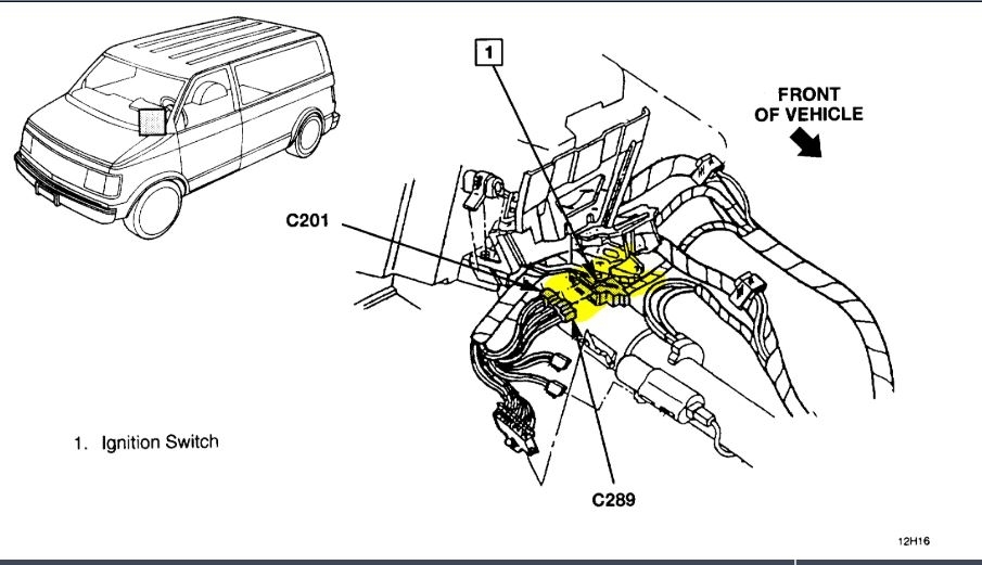
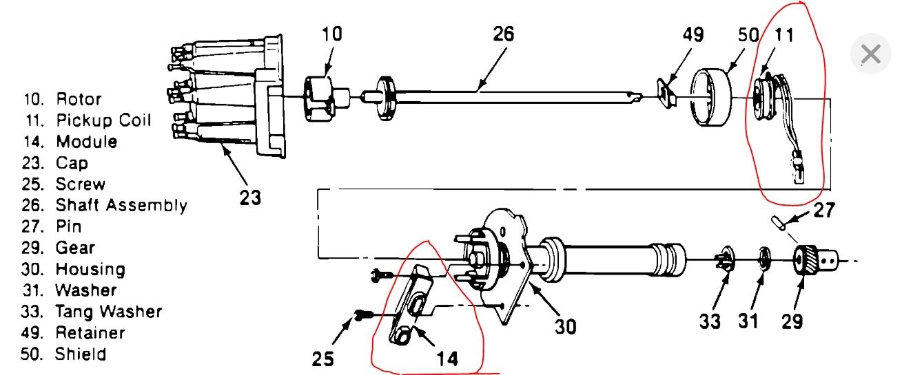
I didn't realize that was the issue. The first suspect on this vehicle is either the pick up coil or ignition control module in the distributor. See picture 1 You indicated replacement of parts in distributor. Were both replaced? Have you checked the coil?

Chances are it has nothing to do with the ignition switch.

If you look at pics 2, 3, and 4, they indicate how to check.

Here are the additions to the pictures.

______________________________________________
CHART TEST DESCRIPTION:
Number(s) below refer to circled number(s) on the diagnostic chart.
1. Two wires are checked, to ensure that an open is not present in a spark plug wire. This step also checks for mechanical problems.
2. A spark indicates the problem must be the distributor cap, rotor, or coil output wire.
3. Normally, there should be battery voltage at the "C" and "+" terminals on the coil connector. Low voltage would indicate an open or a high resistance circuit from the distributor to the coil or ignition switch. If "C" terminal voltage was low, but "+" terminal voltage is 10 volts or more, circuit from "C" terminal to ignition coil or ignition coil primary winding is open.
4. Checks for a shorted module or grounded circuit from the ignition coil to the module. The distributor module should be turned "OFF, " so normal voltage should be about 12 volts.
If the module is turned "ON, " the voltage would be low, but above 1 volt. This could cause the ignition coil to fail from excessive heat.
With an open ignition coil primary winding, a small amount of voltage will leak through the module from the "Batt" to the "Tach" terminal.
5. Applying a voltage (1.35 to 1.50 volts) to module terminal "P" should turn the module "ON" and the "Tach" terminal voltage should drop to about 7-9 volts. This test will determine whether the module or coil is faulty or if the pick-up coil is not generating the proper signal to turn the module "ON." This test can be performed by using a DC test battery with a rating of 1.5 volts. (Such as AA, C, or D cell.) The battery must be a known good battery with a voltage of over 1.35 volts.
6. This should turn "OFF" the module and cause a spark. If no spark occurs, the fault is most likely in the ignition coil because most module problems would have been found before this point in the procedure. A distributor ignition control module tester (J 24642) could determine which is at fault.
______________________________________________

Here are the directions for replacement if you find the module is bad.

REMOVE OR DISCONNECT

NOTE It is not necessary to remove ignition distributor assembly from engine.

- Distributor cap and rotor.
- Connectors from module.
- Two module attaching screws.
- Lift module from housing and remove.

INSTALL OR CONNECT

NOTE: Do not wipe silicone grease from metal face of module or distributor base (where the module seats), when reinstalling the same module. If new module is to be installed clean distributor module base and spread new silicone grease on base and metal face of ignition module. The purpose of the silicone grease is to cool module.

- Module onto housing.
- Module attaching screws. Tighten to 2 Nm (18 lb. In.)
- Connectors to module.
- Rotor and cap.

____________________________

As far as the knock sensor, the last pic attached shows its location. I don't think that is the issue.

___________________________

Let me know if any of this helps.

Take care,
Joe
Was this
answer
helpful?
Yes
No
+1
Tuesday, October 29th, 2019 AT 9:37 PM
Tiny
BOB%
  • MEMBER
  • 67 POSTS
Thank you Joe, I'll re-check the circuits you mentioned and see what happens. Thank you, Bob
Was this
answer
helpful?
Yes
No
Tuesday, October 29th, 2019 AT 10:14 PM
Tiny
JACOBANDNICKOLAS
  • MECHANIC
  • 108,269 POSTS
Welcome back:

You are very welcome. I will watch for your reply.

Take care,
Joe
Was this
answer
helpful?
Yes
No
Wednesday, October 30th, 2019 AT 5:47 PM

Please login or register to post a reply.

Sponsored links