Thursday, June 29th, 2023 AT 3:57 PM
SCION
- MEMBER
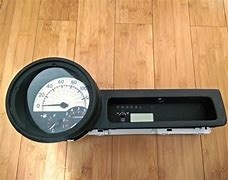
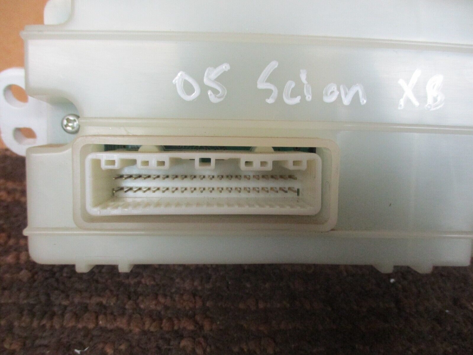
- 2005 SCION XB
- 1.5L
- 4 CYL
- 2WD
- MANUAL
- 60,506 MILES
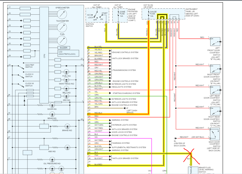
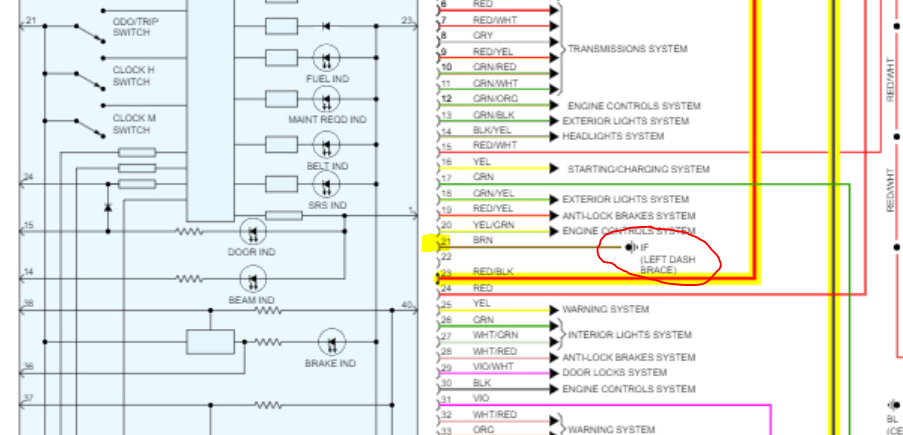
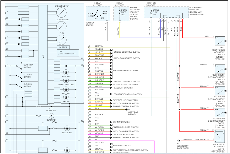
I need a pinout diagram + wire diagram for the vehicle listed above, for the wire diagram. I need it to be something like which color does what, and for the pinout I need it to be like which pin does what. Thanks.