Good morning,
The left side blend door actuator is on the left side of the heater case and is easy replacement.
I attached a picture and procedure.
Change Vehicle Bookmarks Library Request Conversion Calculator Technician's Reference - Collision
Search vehicle information
Community 17 Create Quote
2005 Cadillac STS V6-3.6L VIN 7
Air Temperature Actuator - Left
Vehicle Heating and Air Conditioning Air Door Actuator / Motor Service and Repair Procedures Air Temperature Actuator - Left
AIR TEMPERATURE ACTUATOR - LEFT
AIR TEMPERATURE ACTUATOR REPLACEMENT - LEFT
REMOVAL PROCEDURE
1. Remove the left closeout panel.
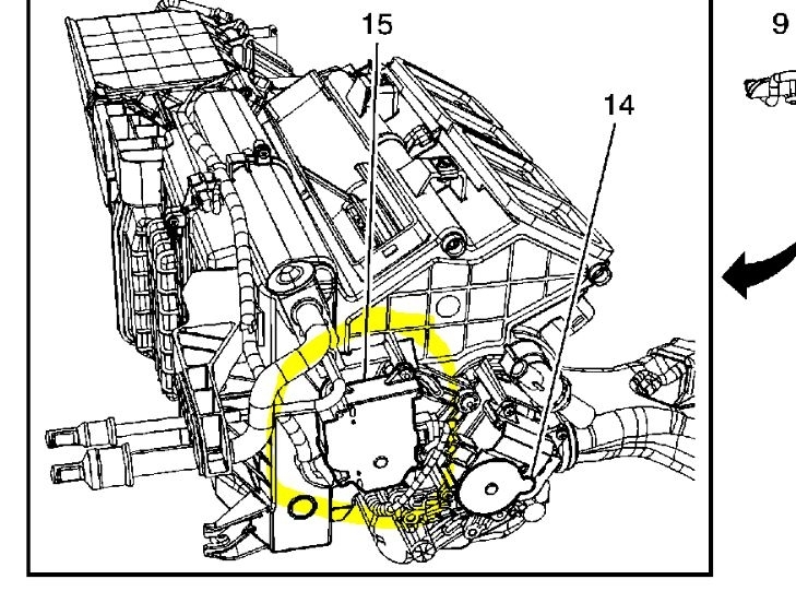
ImageOpen In New TabZoom/Print
2. Disconnect the left air temperature actuator electrical connector from the actuator.
3. Remove the left air temperature actuator screws.
The mode actuator is another story. The dash board has to be removed to gain access to that one. This is a labor intensive job.
Change Vehicle Bookmarks Library Request Conversion Calculator Technician's Reference - Collision
Search vehicle information
Community 17 Create Quote
2005 Cadillac STS V6-3.6L VIN 7
Mode Actuator Replacement
Vehicle Heating and Air Conditioning Air Door Actuator / Motor Service and Repair Procedures Mode Actuator Replacement
MODE ACTUATOR REPLACEMENT
MODE ACTUATOR REPLACEMENT
REMOVAL PROCEDURE
1. Remove the instrument panel (I/P) carrier.
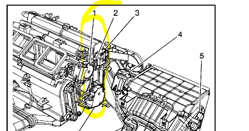
ImageOpen In New TabZoom/Print
2. Disconnect the mode actuator electrical connector.
ImageOpen In New TabZoom/Print
3. Remove the mode actuator screws (3).
Roy
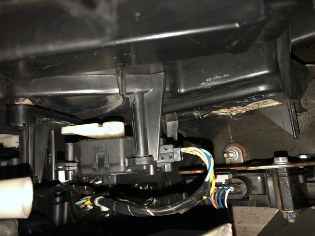
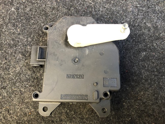
Images (Click to make bigger)
SPONSORED LINKS
Wednesday, January 30th, 2019 AT 3:32 AM