Hi and thanks for using 2carpros.com
The easiest question you asked was left or right... based on the engine's position. Stand on the passenger side front of the engine and that is how you can tell.
As far as determining which head needs removed, the only thing you can do is check compression to help determine where the lower compression is coming from.
https://www.2carpros.com/articles/how-to-test-engine-compression
Now with that being said, this isn't an easy job. As far as what should be replaced, I would recommend the water pump, timing belt, tensioner, guides and head bolts at a minimum. I don't have to mention gaskets and seals.
Okay, here we go. I will start with removal of the left cylinder head which includes timing belt removal.
__________________________________
LEFT CYLINDER HEAD
REMOVAL - CYLINDER HEAD(S)
LEFT CYLINDER HEAD
1) Perform the fuel relief procedure.
2) Disconnect the negative battery cable.
3) Drain cooling system.
4) Remove engine cover.
5) Remove air cleaner element housing.
6) Remove radiator close out panel.
7) Remove radiator core support.
8) Remove radiator fan assembly.
9) Disconnect the fuel line at the fuel rail.
10) Remove the lower intake manifold.
11) Remove the left exhaust manifold.
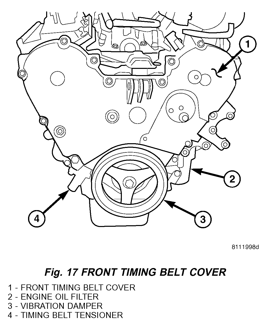
12) Remove the outer timing belt cover.
pic 1
13) Rotate the engine to TDC and align the timing marks (Fig. 19).
14) Remove the timing belt tensioner, timing belt, then reset tensioner (Fig. 19).
15) Remove the left cylinder head cover to cylinder head ground strap.
16) Remove the left cylinder head cover.
17) Remove the left rocker arm assembly.
18) Remove the left camshaft thrust plate.
19) Counterhold the left cam gear and remove the cam gear retaining bolt (Fig. 19).
20) Push the camshaft out of the back of the cylinder head approximately 3.5 inches and remove the cam gear.
21) Remove the front timing belt housing to cylinder head bolts (Fig. 19).
22) Remove the cylinder head bolts in REVERSE of tightening sequence.
23) Remove the cylinder head.
24) Clean and inspect all mating surfaces.
CLEANING
To ensure engine gasket sealing, proper surface preparation must be performed, especially with the use of aluminum engine components and multi-layer steel cylinder head gaskets.
NOTE: Multi-Layer Steel (MLS) head gaskets require a scratch free sealing surface.
Remove all gasket material from cylinder head and block. Be careful not to gouge or scratch the aluminum head sealing surface.
Clean all engine oil passages.
INSPECTION
1) Before cleaning, check for leaks, damage and cracks.
2) Clean cylinder head and oil passages.
pic 2
3) Check cylinder head for flatness (Fig. 23).
4) Cylinder head must be flat within:
- Standard dimension = less than 0.05 mm (0.002 inch)
- Service Limit = 0.2 mm (0.008 inch)
- Grinding Limit = Maximum of 0.2 mm (0.008 inch) is permitted.
CAUTION: 0.20 mm (0.008 inch) MAX is a combined total dimension of the stock removal limit from cylinder head and block top surface (Deck) together.
INSTALLATION - CYLINDER HEAD(S)
LEFT CYLINDER HEAD
CAUTION: THE CYLINDER HEAD GASKETS ARE NOT INTERCHANGEABLE BETWEEN CYLINDER HEADS AND ARE CLEARLY MARKED RIGHT OR LEFT.
The cylinder head bolts are tightened using a torque plus angle procedure. The bolts must be examined BEFORE reuse. If the threads are necked down the bolts must be replaced (Fig. 24).
pic 3
Necking can be checked by holding a scale or straight edge against the threads. If all the threads do not contact the scale the bolt must be replaced (Fig. 26).
CAUTION: When cleaning cylinder head and cylinder block surfaces, DO NOT use a metal scraper because the surfaces could be cut or ground. Use ONLY a wooden or plastic scraper.
1) Clean sealing surfaces of cylinder head and block.
CAUTION: Ensure that the correct head gaskets are used and are oriented correctly on cylinder block.
2) Install head gasket over locating dowels. Ensure the gasket is installed on the correct side of engine.
NOTE: Before installing the cylinder head bolts, lubricate the threads with engine oil.
3) Install the cylinder head over locating dowels, insert and finger tighten the head bolts.
pic 4
4) Tighten the cylinder head bolts in the sequence shown in (Fig. 27). Using the 4 step torque-turn method, tighten according to the following torque values:
- Step 1: All to 61 Nm (45 ft. lbs.)
- Step 2: All to 88 Nm (65 ft. lbs.)
- Step 3: All (again) to 88 Nm (65 ft. lbs.)
- Step 4: + 90° Turn Do not use a torque wrench for this step.
5) Bolt torque after 90° turn should be over 122 Nm (90 ft. lbs.) in the tightening direction. If not, replace the bolt.
6) Install the inner timing cover to cylinder head bolts. Tighten bolts to 54 Nm (40 ft. lbs.).
7) Install camshaft sprocket. Counterhold the camshaft sprocket gear and tighten the camshaft sprocket bolt to 115 Nm plus a 1/4 turn (85 ft. lbs. plus a 1/4 turn).
8) Install the rear camshaft thrust plate.
9) Rotate the camshaft gear to it's alignment mark and check the right camshaft gear and crankshaft gear timing alignment marks.
10) Install the timing belt and tensioner.
11) Install the timing belt front cover.
12) Install the vibration damper.
13) Install the upper engine mount.
14) Install the accessory drive belt tensioner.
15) Install the accessory drive belt idler pulley.
16) Install the left exhaust manifold.
17) Install the exhaust cross over pipe.
18) Install the left rocker arm assembly
19) Install the left cylinder head cover and ground strap.
20) Install lower intake manifold.
21) Install the fuel rail.
22) Install the upper intake manifold.
23) Install the radiator cooling fan assembly.
24) Install the radiator core support.
25) Install the radiator close out panel.
26) Install the air cleaner element housing.
27) Install the engine cover.
28) Fill the coolant system.
29) Connect the negative battery cable.
___________________________________________________________
RIGHT CYLINDER HEAD
REMOVAL - CYLINDER HEAD(S)
RIGHT CYLINDER HEAD
1) Perform the fuel relief procedure.
2) Disconnect the negative battery cable.
3) Drain cooling system.
4) Remove the engine cover.
5) Remove air cleaner element housing.
6) Disconnect the fuel line at the fuel rail.
7) Remove the upper intake manifold.
8) Remove the lower intake manifold.
9) Raise the vehicle.
10) Remove right front tire.
11) Remove right inner splash shield.
pic 5
12) Remove accessory drive belt (Fig. 18).
13) Remove vibration damper (Fig. 17).
14) Remove lower accessory drive belt idler pulley (Fig. 18).
15) Remove the power steering mounting bolts and set the pump aside.
pic 6
16) Remove lower outer timing belt cover bolts (Fig. 17).
17) Raise the vehicle.
18) Remove catalytic converter mounting nuts.
19) Disconnect both oxygen sensor harness connectors.
20) Separate the muffler to tail pipe union.
21) Remove catalytic converter.
22) Remove the exhaust cross over pipe lower bolts.
23) Remove right exhaust manifold.
24) Lower vehicle.
25) Remove the upper accessory drive belt idler pulley (Fig. 18).
26) Remove the belt tensioner (Fig. 18).
27) Support the engine with a block of wood and the floor jack.
28) Remove the upper engine mount.
29) Remove the power steering reservoir bolts and set reservoir aside.
30) Remove the remaining outer timing belt cover bolts and cover.
31) Rotate the engine to TDC and align timing belt marks.
32) Remove the timing belt tensioner and reset the tensioner. (Fig. 17).
33) Remove the timing belt.
pic 7
34) Remove the right valve cover to cylinder head ground strap (Fig. 20).
35) Remove the EGR valve and tube assembly (Fig. 20).
36) Remove the right cylinder head cover (Fig. 20).
pic 8
37) Remove the right rocker arm assembly (Fig. 21).
38) Remove the right rear camshaft thrust plate.
39) Counterhold the cam gear and remove the right cam gear retaining bolt.
pic 9
40) Push the camshaft out of the back of the cylinder head approximately 3.5 inches and remove the cam gear (Fig. 22).
41) Remove the inner timing cover to cylinder head retaining bolts.
42) Remove the cylinder head bolts in REVERSE of tightening sequence (Fig. 22).
NOTE: Because of clearance restrictions when removing the right cylinder head, the front four cylinder head bolts must be loosened, raised and supported with a rubber band before the cylinder head can be removed.
43) Remove the cylinder head (Fig. 22).
44) Clean and inspect all mating surfaces.
CLEANING
To ensure engine gasket sealing, proper surface preparation must be performed, especially with the use of aluminum engine components and multi-layer steel cylinder head gaskets.
NOTE: Multi-Layer Steel (MLS) head gaskets require a scratch free sealing surface.
Remove all gasket material from cylinder head and block. Be careful not to gouge or scratch the aluminum head sealing surface.
Clean all engine oil passages.
INSPECTION
1) Before cleaning, check for leaks, damage and cracks.
2) Clean cylinder head and oil passages.
pic 10
3) Check cylinder head for flatness (Fig. 23).
4) Cylinder head must be flat within:
- Standard dimension = less than 0.05 mm (0.002 inch)
- Service Limit = 0.2 mm (0.008 inch)
- Grinding Limit = Maximum of 0.2 mm (0.008 inch) is permitted.
CAUTION: 0.20 mm (0.008 inch) MAX is a combined total dimension of the stock removal limit from cylinder head and block top surface (Deck) together.
INSTALLATION - CYLINDER HEAD(S)
RIGHT CYLINDER HEAD
CAUTION: THE CYLINDER HEAD GASKETS ARE NOT INTERCHANGEABLE BETWEEN CYLINDER HEADS AND ARE CLEARLY MARKED RIGHT OR LEFT.
pic 12
The cylinder head bolts are tightened using a torque plus angle procedure. The bolts must be examined BEFORE reuse. If the threads are necked down the bolts must be replaced (Fig. 24).
Necking can be checked by holding a scale or straight edge against the threads. If all the threads do not contact the scale the bolt must be replaced (Fig. 24).
CAUTION: When cleaning cylinder head and cylinder block surfaces, DO NOT use a metal scraper because the surfaces could be cut or ground. Use ONLY a wooden or plastic scraper.
1) Clean sealing surfaces of cylinder head and block.
CAUTION: Ensure that the correct head gaskets are used and are oriented correctly on cylinder block.
2) Install head gasket over locating dowels. Ensure the gasket is installed on the correct side of engine.
NOTE: Before installing the cylinder head bolts, lubricate the threads with engine oil.
3) Insert the front four cylinder head bolts into the cylinder head. Pull the bolts up to the top of their travel and retain with rubber bands.
4) Install the cylinder head over locating dowels and finger tighten the head bolts.
pic 13
5) Tighten the cylinder head bolts in the sequence shown in (Fig. 25). Using the 4 step torque-turn method, tighten according to the following torque values:
- Step 1: All to 61 Nm (45 ft. lbs.)
- Step 2: All to 88 Nm (65 ft. lbs.)
- Step 3: All (again) to 88 Nm (65 ft. lbs.)
- Step 4: + 90° Turn Do not use a torque wrench for this step.
6) Bolt torque after 90° turn should be over 122 Nm (90 ft. lbs.) in the tightening direction. If not, replace the bolt.
7) Install the inner timing cover to cylinder head bolts. Tighten bolts to 54 Nm (40 ft. lbs.).
8) Install camshaft sprocket. Counterhold the camshaft sprocket gear and tighten the camshaft sprocket bolt to 102 Nm plus a 1/4 turn (75 ft. lbs. plus a 1/4 turn).
9) Install the rear camshaft thrust plate.
10) Rotate the camshaft gear to it's alignment mark and check the left camshaft gear and crankshaft gear timing alignment marks.
11) Install the timing belt and tensioner.
12) Install the timing belt outer cover.
13) Install the power steering reservoir.
14) Install the vibration damper.
15) Install the upper engine mount.
16) Install the accessory drive belt tensioner.
17) Install the accessory drive belt idler pulley.
18) Install the right exhaust manifold.
19) Install the exhaust cross over pipe.
20) Install the catalytic converter and exhaust system.
21) Connect both oxygen sensors.
22) Lower the vehicle.
23) Install the right rocker arm assembly
24) Install the right cylinder head cover and ground strap.
25) Install lower intake manifold.
26) Install the fuel rail.
27) Install the upper intake manifold.
28) Install the air cleaner element housing.
29) Install the engine cover.
30) Fill the coolant system.
31) Connect the negative battery cable.
_____________________________________________
Timing belt removal
TIMING BELT AND SPROCKETS
REMOVAL - TIMING BELT
TIMING VERIFICATION
Remove the outer timing covers. Rotate the crankshaft until the pointer on the crankshaft sprocket aligns the TDC mark on the oil pump. Check to determine if the camshaft sprocket timing marks are aligned with the marks on the inner timing cover. It may take an additional full revolution of the crankshaft before the camshaft sprocket marks are aligned (Fig. 169).
CAUTION: The 3.5L is NOT a freewheeling engine. Therefore, loosen the valve train rocker assemblies before servicing the timing drive.
1) Perform fuel pressure release procedure.
2) Disconnect negative battery cable.
3) Remove both cylinder head covers and loosen the rocker arm assemblies.
4) Remove the front timing belt cover.
5) Mark belt running direction, if timing belt is to be reused.
CAUTION: When aligning timing marks, always rotate engine by turning the crankshaft. Failure to do so will result in valve and/or piston damage.
pic 14
6) Rotate engine clockwise until crankshaft mark aligns with the TDC mark on oil pump housing and the camshaft sprocket timing marks are aligned with the marks on the rear cover (Fig. 169)
7) Remove the timing belt tensioner (Fig. 169) and remove timing belt.
8) Inspect the tensioner for fluid leakage.
9) Inspect the pivot and bolt for free movement, bearing grease leakage, and smooth rotation. If not rotating freely, replace the arm and pulley assembly
10) When tensioner is removed from the engine it is necessary to compress the plunger into the tensioner body
CAUTION: Index the tensioner in the vise the same way it is installed on the engine. This ensures proper pin orientation when tensioner is installed on the engine.
pic 15
a) Place the tensioner into a vise and SLOWLY compress the plunger (Fig. 170). Total bleed down of tensioner should take about 5 minutes.
b) When plunger is compressed into the tensioner body install a pin through the body and plunger to retain plunger in place until tensioner is installed.
INSPECTION
TIMING VERIFICATION
pic 16
Remove the outer timing covers. Rotate the crankshaft until the pointer on the crankshaft sprocket (10) (Fig. 175) aligns the TDC mark on the oil pump (9). Check to determine if the camshaft sprocket (2, 7) timing marks (1, 8) are aligned with the marks on the inner timing cover. It may take an additional full revolution of the crankshaft before the camshaft sprocket marks are aligned.
INSPECTION - TIMING BELT
1) Remove front timing belt cover.
pic 17
2) Inspect both sides of the timing belt. Replace belt if any of the following conditions exist (Fig. 176):
a) Hardening of back rubber back side is glossy without resilience and leaves no indent when pressed with fingernail.
b) Cracks on rubber back.
c) Cracks or peeling of canvas.
d) Cracks on rib root.
e) Cracks on belt sides.
f) Missing teeth.
g) Abnormal wear of belt sides. The sides are normal if they are sharp as if cut by a knife.
h) Vehicle mileage or time at component maintenance requirement.
3) If none of the above conditions are seen on the belt, the front timing belt cover can be installed.
TIMING BELT
CAUTION: If camshafts have moved from the timing marks, always rotate camshaft towards the direction nearest to the timing marks (DO NOT TURN CAMSHAFTS A FULL REVOLUTION OR DAMAGE to valves and/or pistons could result).
pic 18
1) Align the crankshaft sprocket (10) (Fig. 179) with the TDC mark (9) on oil pump cover.
2) Align the camshaft sprockets (2, 7) timing reference marks (1, 8) with the marks on the rear cover.
3) Install the timing belt starting at the crankshaft sprocket (10) going in a counterclockwise direction. Install the belt around the last sprocket. Maintain tension on the belt as it is positioned around the tensioner pulley (11).
NOTE: If the camshaft gears have been removed it is only necessary to have the camshaft gear retaining bolts installed to a snug torque at this time.
4) Holding the tensioner pulley (11) against the belt, install the tensioner into the housing and tighten to 28 Nm (250 inch lbs.). Each camshaft sprocket mark should remain aligned the cover marks.
5) When tensioner is in place pull retaining pin to allow the tensioner to extend to the pulley bracket.
6) Rotate crankshaft sprocket 2 revolutions and check the timing marks on the camshafts and crankshaft. The marks should line up within their respective locations. If marks do not line up, repeat procedure.
NOTE: If camshaft gears have been removed and timing is correct, counterhold and tighten the camshaft gears to final torque specification.
7) Install the front timing belt cover.
8) Tighten the rocker arm assemblies and install the cylinder head covers.
9) Connect negative battery cable.
__________________________________________________
Let me know if this helps or if you have other questions.
Take care,
Joe
Images (Click to make bigger)
SPONSORED LINKS
Sunday, January 27th, 2019 AT 8:47 PM