TIMING BELT
Removal
Noting position for installation reference, disconnect secondary wires from spark plugs. Remove spark plugs.
Disconnect negative battery cable. Remove air intake resonators. Remove power steering pressure hose bracket from lifting eye, and position aside.
Support engine from above using Three Bar Engine Support (D88L-6000-A) or equivalent. Remove upper timing belt cover.
Mark position of upper front engine mount before removal. Remove upper front mount. If equipped, disconnect coolant level sensor connector from coolant recovery reservoir. Remove retainers attaching recovery reservoir, and position aside. Remove upper front mount insulator.
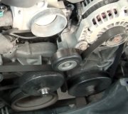
Loosen water pump pulley bolts. Remove serpentine drive belt. Remove drive belt idler pulley from alternator mounting bracket. Remove water pump pulley.
Remove center timing belt cover. Raise and support vehicle. Remove crankshaft pulley. See Fig. 3 . Remove lower timing belt cover. Remove valve cover.
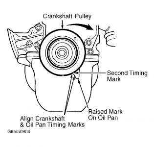
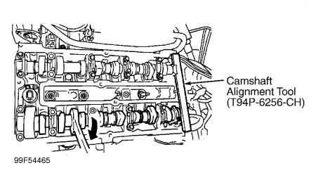
Temporarily install crankshaft pulley. Rotate crankshaft to align timing mark on block with larger notch on pulley. See Fig. 1 . Use Camshaft Alignment Tool (T94P-6256-CH) or equivalent to align camshafts. See Fig. 2 . Install tool in slots on camshafts at rear of engine.
Loosen timing belt tensioning pulley. See Fig. 4 . Move pulley to relieve tension on timing belt, and retighten pulley. If reusing timing belt, mark direction of rotation before removal. Remove timing belt.
Fig. 1: Aligning Crankshaft Timing Marks
Courtesy of FORD MOTOR CO.
Fig. 2: Installing Camshaft Alignment Tool
Courtesy of FORD MOTOR CO.
Fig. 3: Exploded View Of Timing Belt Components
Courtesy of FORD MOTOR CO.
Fig. 4: Identifying Timing Belt Tensioner
Courtesy of FORD MOTOR CO.
Installation
Temporarily install crankshaft pulley. Ensure crankshaft pulley timing marks are aligned. See Fig. 1 . Ensure camshaft alignment tool is still installed.
Install tensioner and retaining bolt (if necessary). Remove crankshaft pulley.
Install timing belt on crankshaft sprocket. Working in a clockwise direction, install timing belt around camshaft sprockets. Ensure timing belt span between crankshaft sprocket and exhaust camshaft is not loose. Ensure timing belt is aligned on all sprockets.
Install lower timing belt cover. Apply Silicone Gasket Sealer (F1AZ 9562-A) or equivalent to crankshaft keyway. Install crankshaft pulley. Tighten bolt to specification. See TORQUE SPECIFICATIONS .
Ensure crankshaft timing marks are aligned. See Fig. 1 . Loosen timing belt tensioner pulley, and allow spring to pull pulley against timing belt. Remove camshaft alignment tool. Rotate crankshaft clockwise 2 full revolutions.
Tighten timing belt tensioner pulley to specification. See TORQUE SPECIFICATIONS . Align crankshaft timing marks. See Fig. 1 . Ensure camshafts are still aligned by installing Camshaft Alignment Tool (T94P-6256-CH) on rear of camshafts. If crankshaft and camshaft alignment is correct, continue with installation procedure.
If camshaft alignment tool cannot be installed on camshafts with crankshaft at TDC, hold camshaft sprocket with Camshaft Sprocket Holding Tool (T74P-6256-B) or spanner wrench. Loosen, but do not remove, camshaft sprocket center bolt. Rotate camshafts until camshaft alignment tool can be installed on rear of camshafts. Crankshaft MUST remain at TDC when aligning camshafts. Tighten camshaft sprocket center bolts to specification.
Install timing belt covers. Install crankshaft pulley. Tighten bolt to specification. Install valve cover. Install spark plugs.
Install upper front engine mount. Remove engine support tool. Install water pump pulley. Install serpentine belt idler pulley and serpentine bolt.
Install coolant recovery reservoir. To complete installation, reverse removal procedure.
SPONSORED LINKS
Friday, January 2nd, 2009 AT 11:33 PM