Hi and thanks for using 2CarPros.
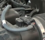
Honestly, we only recommend direct fit components. In this case, all I can say is it should. However, before you go to all the work, inspect both engines. Locate all sensors to confirm they are the same. Actually, I would suggest switching them between the two engines. Also, I would switch the injectors and throttle body and make sure the exhaust manifolds are the same.
______________________________________
Remember, the engine itself should be the same, but it is all the components that go on it which can be different or located in different locations.
___________________________________
Here are directions for engine replacement. All attached pictures correlate with these directions.
ENGINE REPLACEMENT
Engine Replacement
Removal Procedure
1. Disconnect the negative battery cable.
2. Remove the throttle body air inlet duct.
3. Remove the cruise control cable from the engine and reposition the cable away from the engine.
4. Caution: In order to avoid possible injury or vehicle damage, always replace the accelerator control cable with a NEW cable whenever you remove the engine from the vehicle.
In order to avoid cruise control cable damage, position the cable out of the way while you remove or install the engine. Do not pry or lean against the cruise control cable and do not kink the cable. You must replace a damaged cable.
Remove and discard the accelerator control cable from the engine and reposition the cable away from the engine.
5. Drain the cooling system. Refer to Draining and Filling Cooling System.
6. Disconnect the radiator hoses from the engine.
7. Disconnect the heater hoses from the engine.
8. Remove the engine mount struts.
9. Important: Relieve the fuel pressure.
Disconnect the fuel lines at quick connects.
10. Remove the upper engine wiring harness from engine and transmission.
11. Remove the vacuum hoses from the engine.
12. Remove the vacuum brake booster hose.
13. Remove the automatic transaxle range selector cable.
14. Raise and support the vehicle. Refer to Vehicle Lifting.
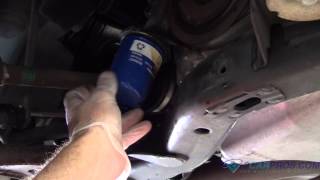
15. Drain the engine oil.
16. Remove the lower engine wiring harness from engine and transmission.
17. Remove the 3-way catalytic converter (TWC).
18. Remove rear propeller shaft.
19. Remove the front tires and wheels.
20. Remove lower radiator baffle assembly.
21. Remove the engine splash shields.
22. Remove the stabilizer shaft links from the lower control arms.
23. Remove the tie rod ends from the steering knuckles.
24. Remove the lower ball joints from the knuckles.
25. Remove A/C compressor bolts and position compressor aside.
26. Disconnect the drive axles from the transaxle.
27. Secure the drive axles to the steering knuckle/struts.
28. Caution: Failure to disconnect the intermediate shaft from the rack and pinion steering gear stub shaft can result in damage to the steering gear and/or intermediate shaft. This damage may cause loss of steering control which could result in an accident and possible personal injury
Remove the intermediate shaft pinch bolt from the steering gear.
Picture 1
29. Lower the vehicle until the frame contacts the trans-axle table.
30. Remove the frame bolts.
31. Raise the vehicle in order to separate the power-train/frame assembly from the vehicle.
32. Remove the starter.
33. Remove the engine flywheel to torque converter bolts.
Picture 2
34. Install engine hoist to engine.
35. Remove engine mount to frame nuts.
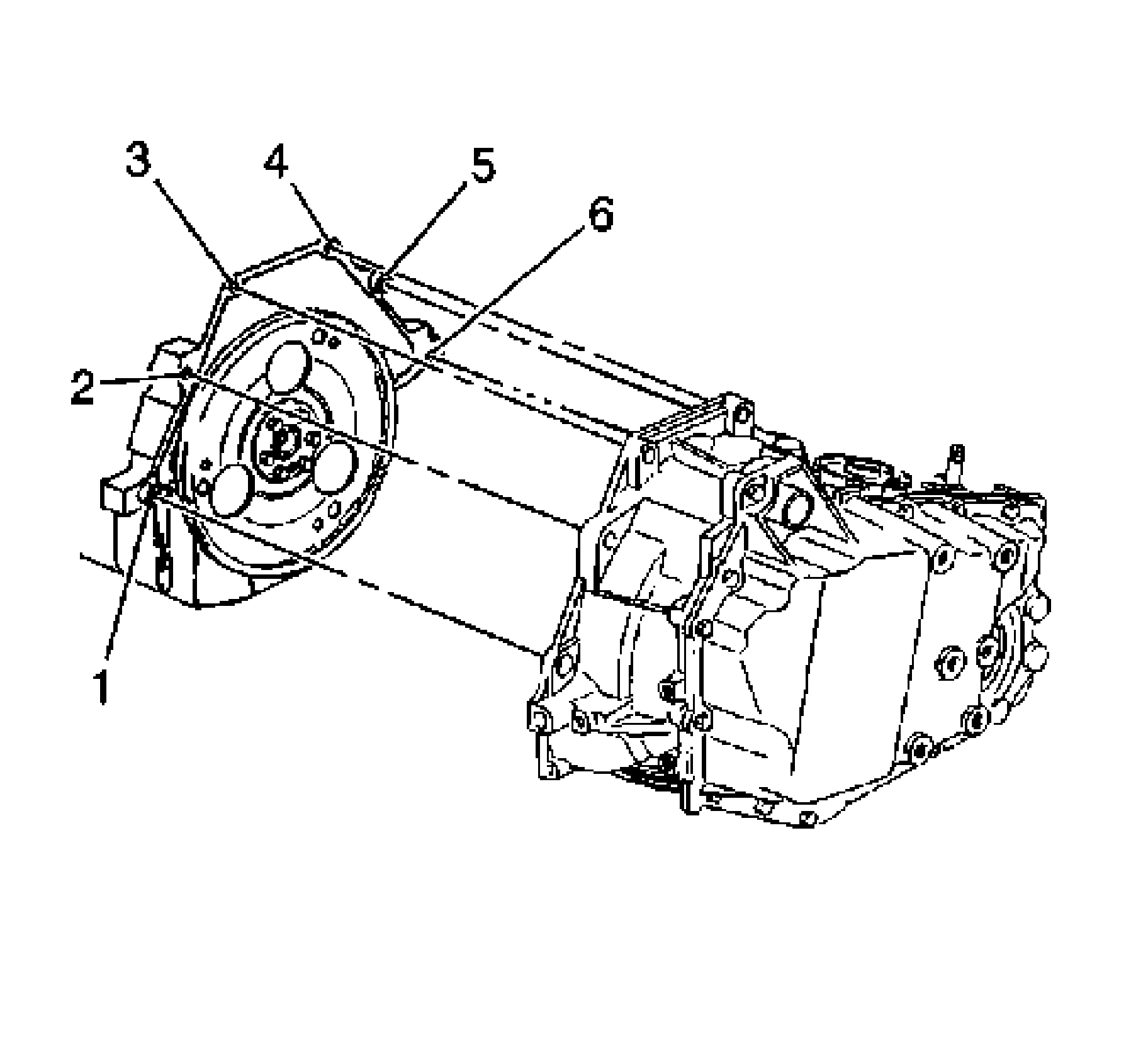
36. Remove the engine-to-trans-axle bolts (3, 4, 5, 6) and studs (1, 2).
37. Separate and remove the engine from the trans-axle/frame and install to the engine stand.
Installation Procedure
Picture 3
1. Remove the engine from the engine stand.
2. Install and align the engine to the translatable/frame.
3. Notice: Refer to Fastener Notice in Service Precautions.
Install the engine-to-trans-axle bolts (3, 4, 5, 6) and studs (1, 2).
Tighten the bolts (3, 4, 5, 6) and studs (1, 2) to 75 Nm (55 ft. Lbs.).
4. Install engine mount to frame nuts.
Tighten nuts to 43 Nm (32 ft. Lbs.).
5. Remove the engine hoist from the engine.
6. Install the engine flywheel to torque converter bolts.
Tighten bolts to 62 Nm (46 ft. Lbs.).
7. Install the starter.
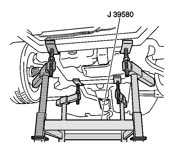
8. Position the trans-axle table with the power-train/frame under the vehicle.
Picture 4
9. Lower the vehicle until the frame contacts the trans-axle table.
10. Install the new frame bolts.
11. Raise and support the vehicle. Refer to Vehicle Lifting.
12. Remove the trans-axle table.
13. Caution: When installing the intermediate shaft make sure that the shaft is seated prior to pinch bolt installation. If the pinch bolt is inserted into the coupling before shaft installation, the two mating shafts may disengage. Disengagement of the two mating shafts will cause loss of steering control which could result in personal injury.
Install the intermediate shaft pinch bolt to steering gear.
14. Install the drive axles to the trans-axle.
15. Install A/C compressor and bolts.
16. Install the lower ball joints to the knuckles.
17. Install the tie rod ends to the steering knuckles.
18. Install the stabilizer shaft links to the lower control arms.
19. Install the engine splash shields.
20. Install lower radiator baffle.
21. Install the front tires and wheels.
22. Install the TWC.
23. Install the lower engine wiring harness to engine and transmission.
24. Install rear propeller shaft.
25. Lower the vehicle.
26. Install the automatic trans-axle range selector cable.
27. Install the vacuum brake booster hose.
28. Install the vacuum hoses to the engine.
29. Install the upper engine wiring harness to engine and transmission.
30. Install the fuel lines at quick connects.
31. Install the engine mount struts.
32. Connect the heater hoses to the engine.
33. Connect the radiator hoses to the engine.
34. Caution: In order to avoid possible injury or vehicle damage, always replace the accelerator control cable with a new cable whenever you remove the engine from the vehicle.
In order to avoid cruise control cable damage, position the cable out of the way while you remove or install the engine. Do not pry or lean against the cruise control cable and do not kink the cable. You must replace a damaged cable.
Install the new accelerator control cable to the engine.
35. Install the cruise control cable to the engine.
36. Install the throttle body air inlet duct.
37. Fill the cooling system with engine coolant. Refer to Draining and Filling Cooling System.
38. Adjust the trans-axle fluid level. Refer to the following information:
Capacities - Approximate Fluid
Fluid and Lubricant Recommendations
39. Fill the engine with oil.
40. Connect the negative battery cable.
41. Perform the CKP system variation learn procedure.
42. Inspect for proper fluid levels and possible fluid leaks.
____________________________________
Let me know if this helps or if you have other questions.
Take care,
Joe
Images (Click to make bigger)
SPONSORED LINKS
Saturday, February 2nd, 2019 AT 9:35 PM