Hi,
It comes out through the bottom. Here are the directions, step by step, explaining how to remove and replace the engine. The attached pics correlate with the directions.
____________________________
2014 Chevy Truck Trax AWD (CANADA) L4-1.4L Turbo
Engine Replacement
Vehicle Engine, Cooling and Exhaust Engine Service and Repair Removal and Replacement Engine Replacement
ENGINE REPLACEMENT
Engine Replacement
Removal Procedure
1. Remove the battery and battery tray. Refer to Battery Tray Replacement See: Battery Tray > Removal and Replacement > Battery Tray Replacement.
2. Relieve the fuel system pressure. Refer to Fuel Pressure Relief See: Fuel Pressure Release > Procedures > Fuel Pressure Relief.
3. Recover the refrigerant. Refer to Refrigerant Recovery and Recharging (R-134a) See: Heating and Air Conditioning > Procedures > Refrigerant Recovery and Recharging (R-134a).
4. Remove the front tire and wheel assembly. Refer to Tire and Wheel Removal and Installation See: Wheels and Tires > Removal and Replacement > Tire and Wheel Removal and Installation.
5. Remove the front bumper fascia. Refer to Front Bumper Fascia Replacement (Chevrolet) Front Bumper Fascia Replacement (Buick).
6. Drain the cooling system. Refer to Cooling System Draining and Filling See: Cooling System > Procedures > Cooling System Draining and Filling.
Pic 1
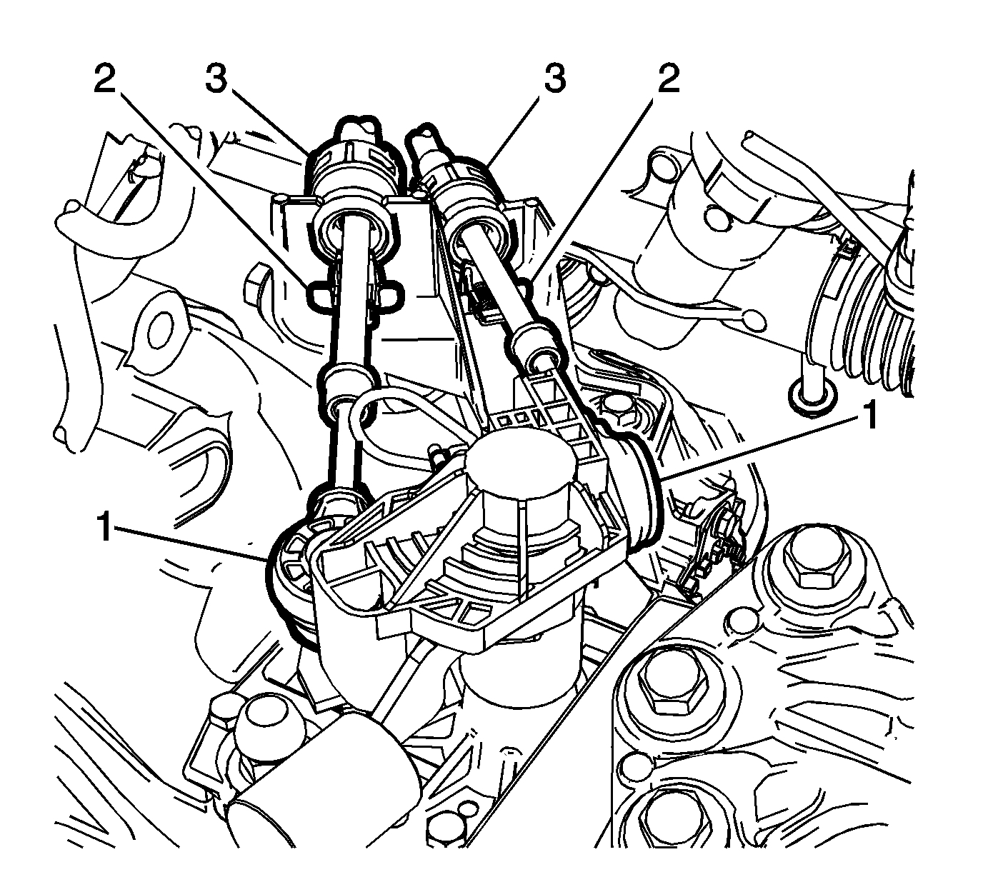
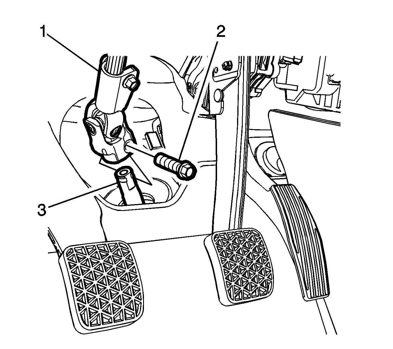
7. Remove the lower intermediate steering shaft bolt (2) and slide the shaft away from steering column. Refer to Intermediate Steering Shaft Replacement (NJ1) See: Steering Shaft > Removal and Replacement > Intermediate Steering Shaft Replacement (Non-Variable Ratio, Electric)Intermediate Steering Shaft Replacement (N40) See: Steering Shaft > Removal and Replacement > Intermediate Steering Shaft Replacement (Non-Variable Ratio).
Pic 2
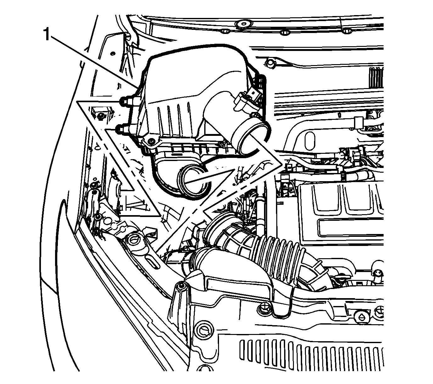
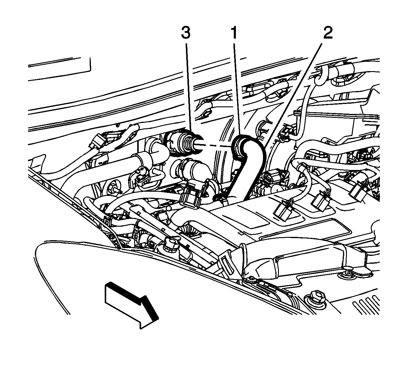
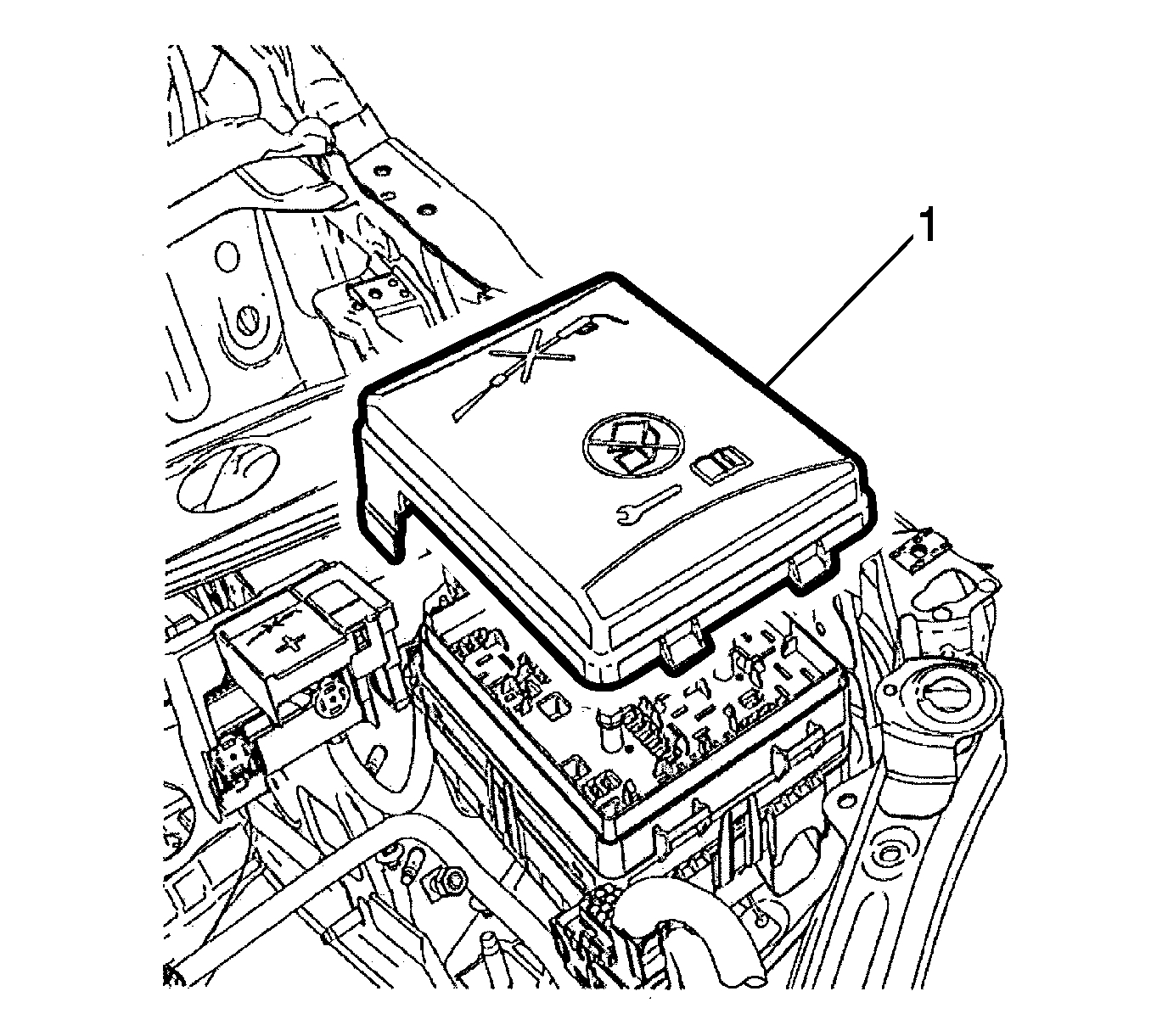
8. Remove the air cleaner assembly (1). Refer to Air Cleaner Assembly Replacement See: Air Cleaner Housing > Removal and Replacement > Air Cleaner Assembly Replacement.
Pic 3
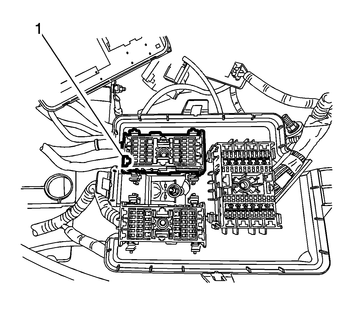
9. Remove the junction block cover (1).
Pic 4
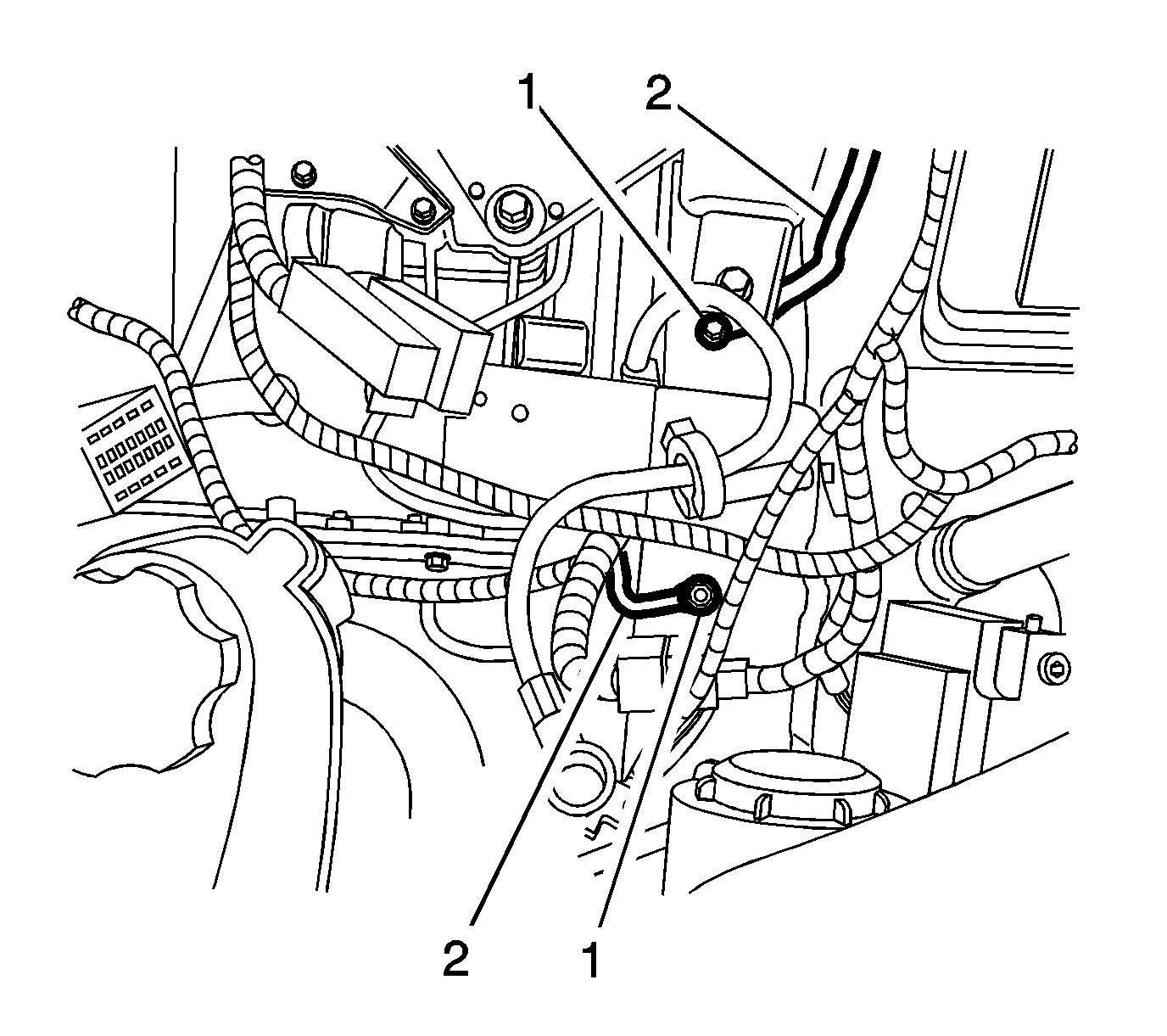
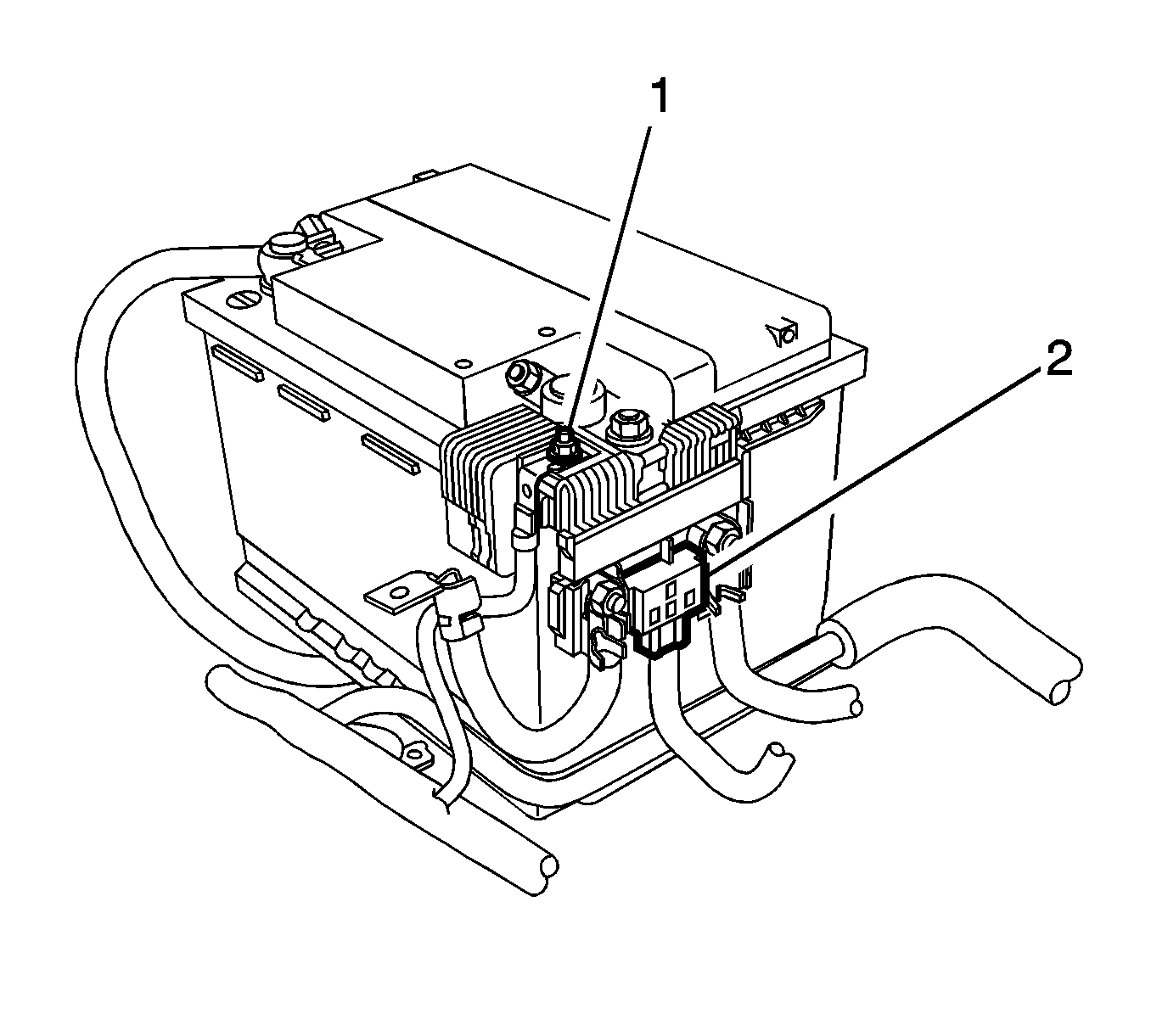
10. Remove the positive battery cable nut (1) from the junction block.
11. Remove the positive battery cable (2) from the junction block.
Pic 5
12. Remove the positive cable nut (1) and battery positive cable from the battery positive cable junction block.
13. Disconnect the body wiring master harness connector (2) from the battery positive cable junction block.
Pic 6
14. Remove the junction block nut (1).
15. Remove the junction block bolts (2).
16. Disconnect the wiring harness from the junction block base.
17. Remove the junction block (3) from the base.
18. Disconnect the wiring harness plug from the front compartment fuse block.
Pic 7
19. Reposition the wiring harness (1) on top of the engine.
Pic 8
20. Remove the ground nuts (1) and reposition the wiring harness (2) aside.
21. Disconnect the power vacuum brake booster vacuum sensor electrical connector, if equipped.
22. Disconnect the heater inlet hose from the heater core. Refer to Heater Inlet Hose Replacement (LUJ, LUV) See: Heater Hose > Removal and Replacement > Heater Inlet Hose ReplacementHeater Inlet Hose Replacement (2H0) See: Heater Hose > Removal and Replacement > Heater Inlet Hose Replacement.
Pic 9
23. Disconnect the heater outlet hose (1) from the heater core. Refer to Heater Outlet Hose Replacement (2H0) See: Heater Hose > Removal and Replacement > Heater Outlet Hose Replacement (Front)Heater Outlet Hose Replacement (LUJ, LUV) See: Heater Hose > Removal and Replacement > Heater Outlet Hose Replacement (Front)Heater Outlet Hose Replacement (LUJ, LUV Rear) See: Heater Hose > Removal and Replacement > Heater Outlet Hose Replacement (Rear).
Pic 10
24. If equipped with an automatic transmission, disconnect the transmission range selector lever cable terminal (1) from the transmission manual shift lever pin.
25. Remove the transmission range selector lever cable (2) from the cable bracket.
Pic 11
26. If equipped with manual transmission, disconnect the shift lever and selector lever cable end (1) from the transmission shift lever and selector lever.
27. Pull the cable retainers (2) to release the shift lever and selector lever cable from the shift lever and selector lever cable bracket.
28. Disconnect the shift lever and selector lever cable from the shift lever and selector lever cable bracket.
Pic 12
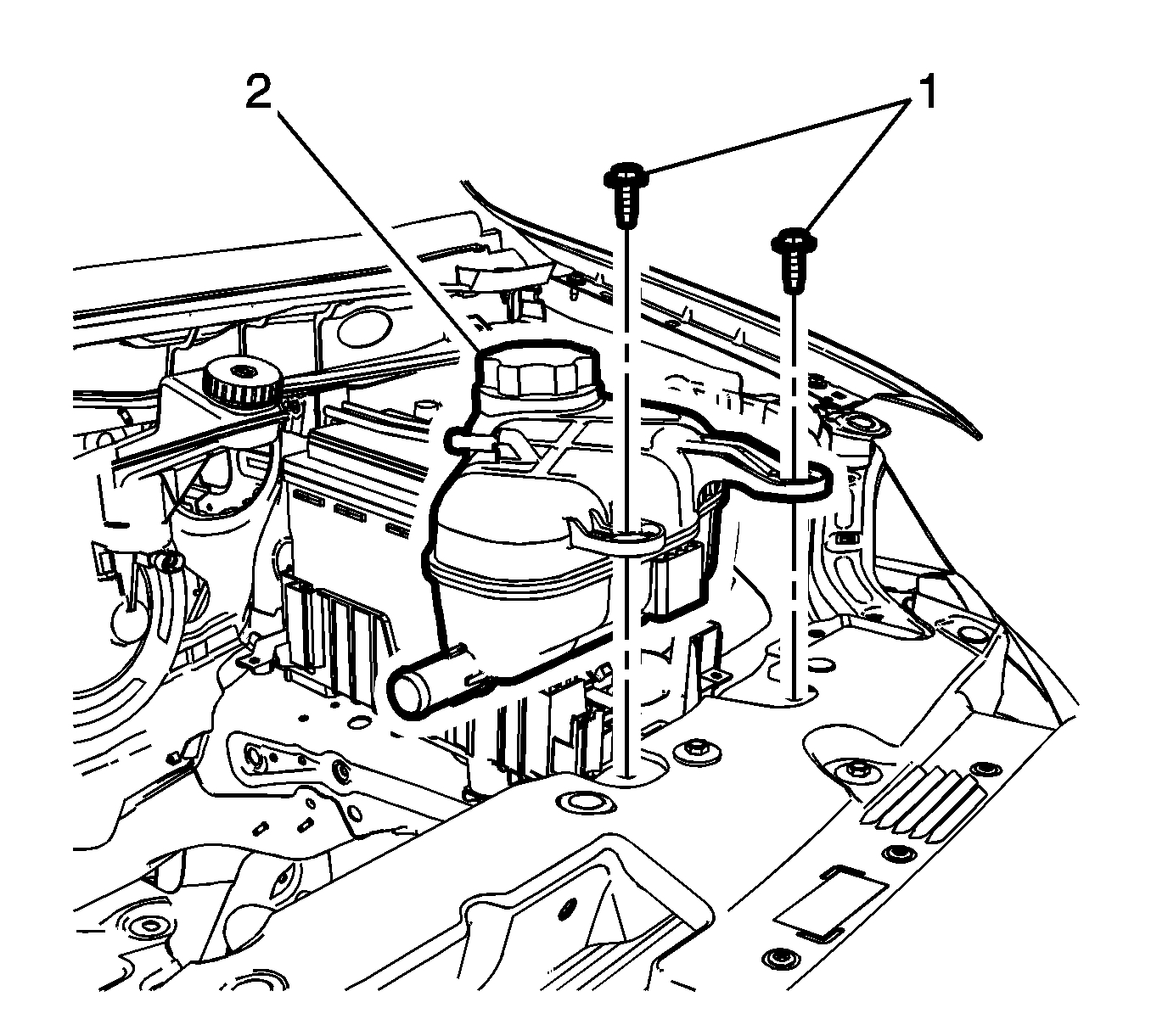
29. Remove the radiator surge tank (2) and position aside. Refer to Radiator Surge Tank Replacement (LUV, 2H0, LUJ) See: Coolant Reservoir > Removal and Replacement > Radiator Surge Tank Replacement.
30. Disconnect the fan connector.
Pic 13
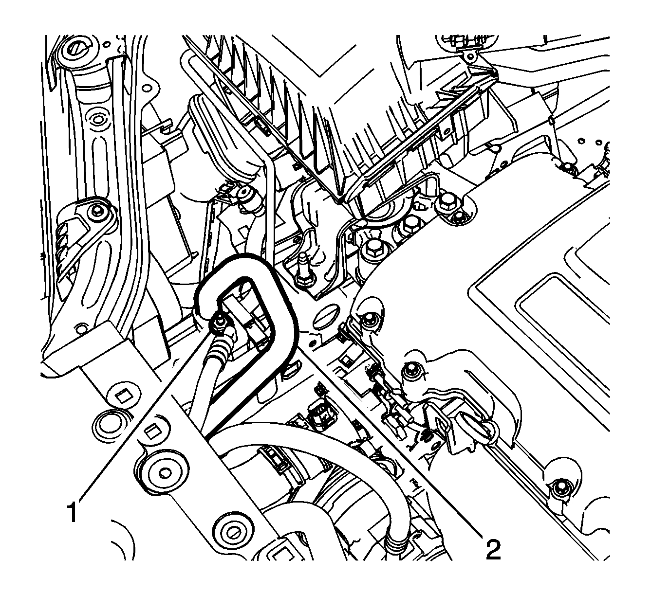
31. Remove air conditioning compressor and condenser hose nut (1).
32. Remove air conditioning compressor and condenser hose (2) from refrigerant hose.
Pic 14
33. Disconnect the fuel feed pipe. Refer to Plastic Collar Quick Connect Fitting Service See: Coolant Line/Hose > Procedures > Plastic Collar Quick Connect Fitting Service.
Pic 15
34. Disconnect the evaporative emission pipe (1). Refer to Plastic Collar Quick Connect Fitting Service See: Coolant Line/Hose > Procedures > Plastic Collar Quick Connect Fitting Service.
Pic 16
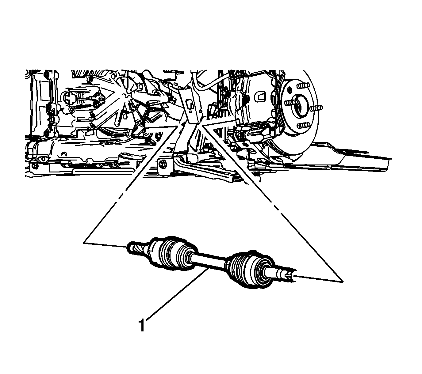
35. Remove the wheel drive shafts. Refer to Front Wheel Drive Shaft Replacement - Left Side See: Axle Shaft Assembly > Removal and Replacement > Front Wheel Drive Shaft Replacement - Left Side and Front Wheel Drive Shaft Replacement - Right Side See: Axle Shaft Assembly > Removal and Replacement > Front Wheel Drive Shaft Replacement - Right Side.
36. Remove the front exhaust pipe. Refer to Exhaust Front Pipe Replacement (LUV) See: Heat Shield, Exhaust > Removal and Replacement > Exhaust Front Pipe ReplacementExhaust Front Pipe Replacement See: Heat Shield, Exhaust > Removal and Replacement > Exhaust Front Pipe Replacement.
Pic 17
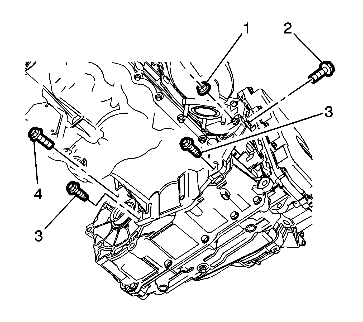
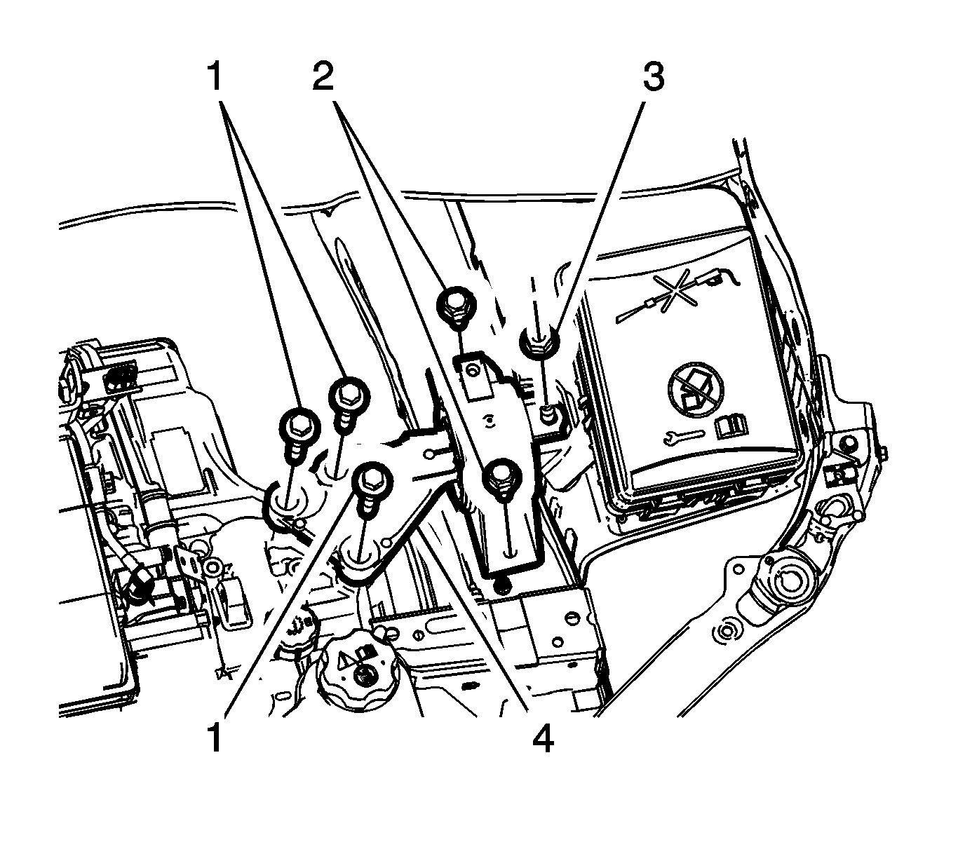
37. If equipped with an automatic transmission, remove the lower transmission nut (1) and the lower transmission bolts (2, 3, 4).
Pic 18
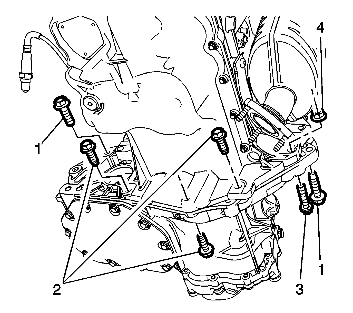
38. If equipped with manual transmission, remove the lower transmission bolt (3) and nut (4).
39. Remove the lower transmission bolts (1, 2).
Pic 19
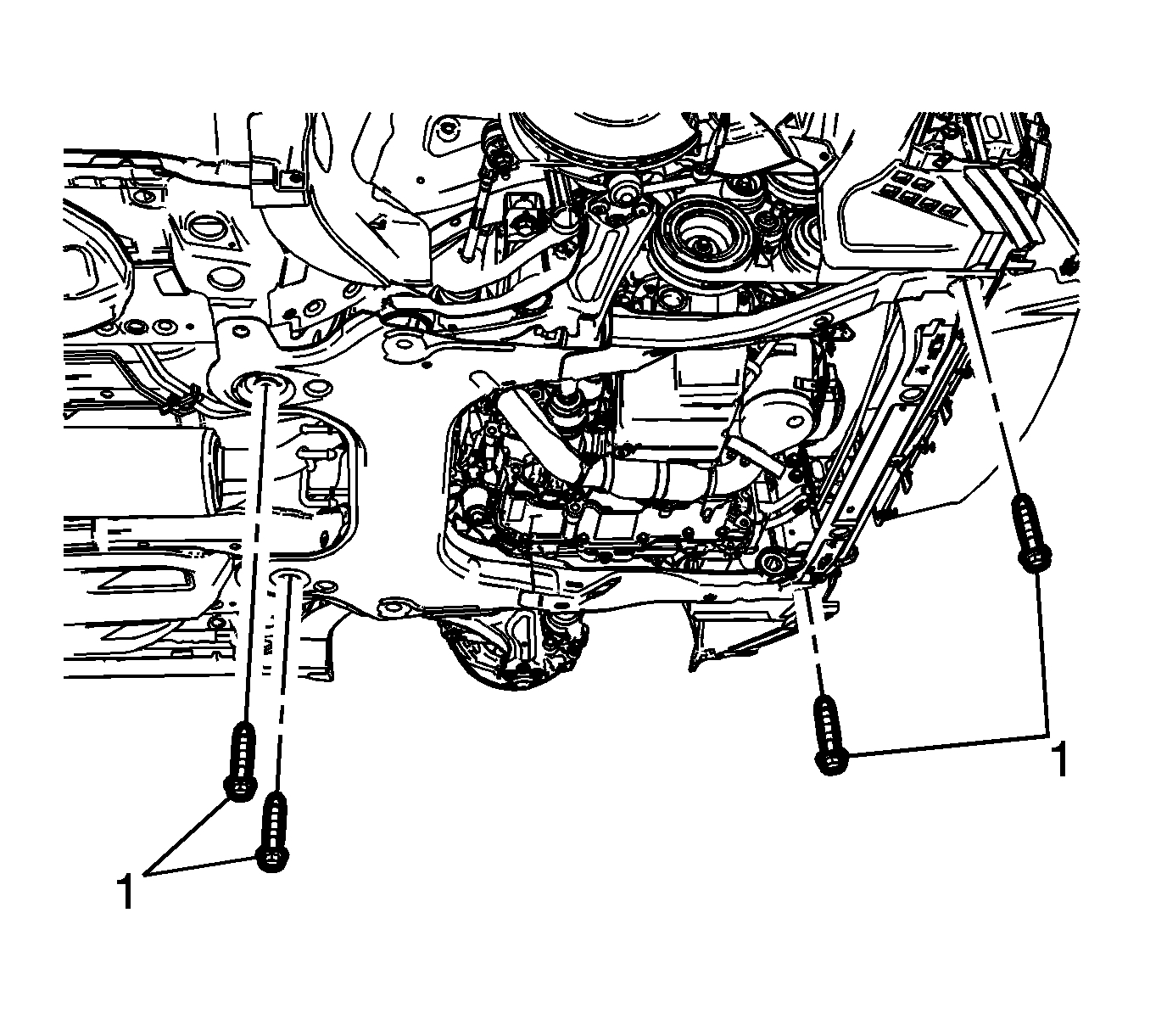
40. Remove the frame front bolts (1).
41. Position the lift table under the powertrain and support with blocks of wood.
Pic 20
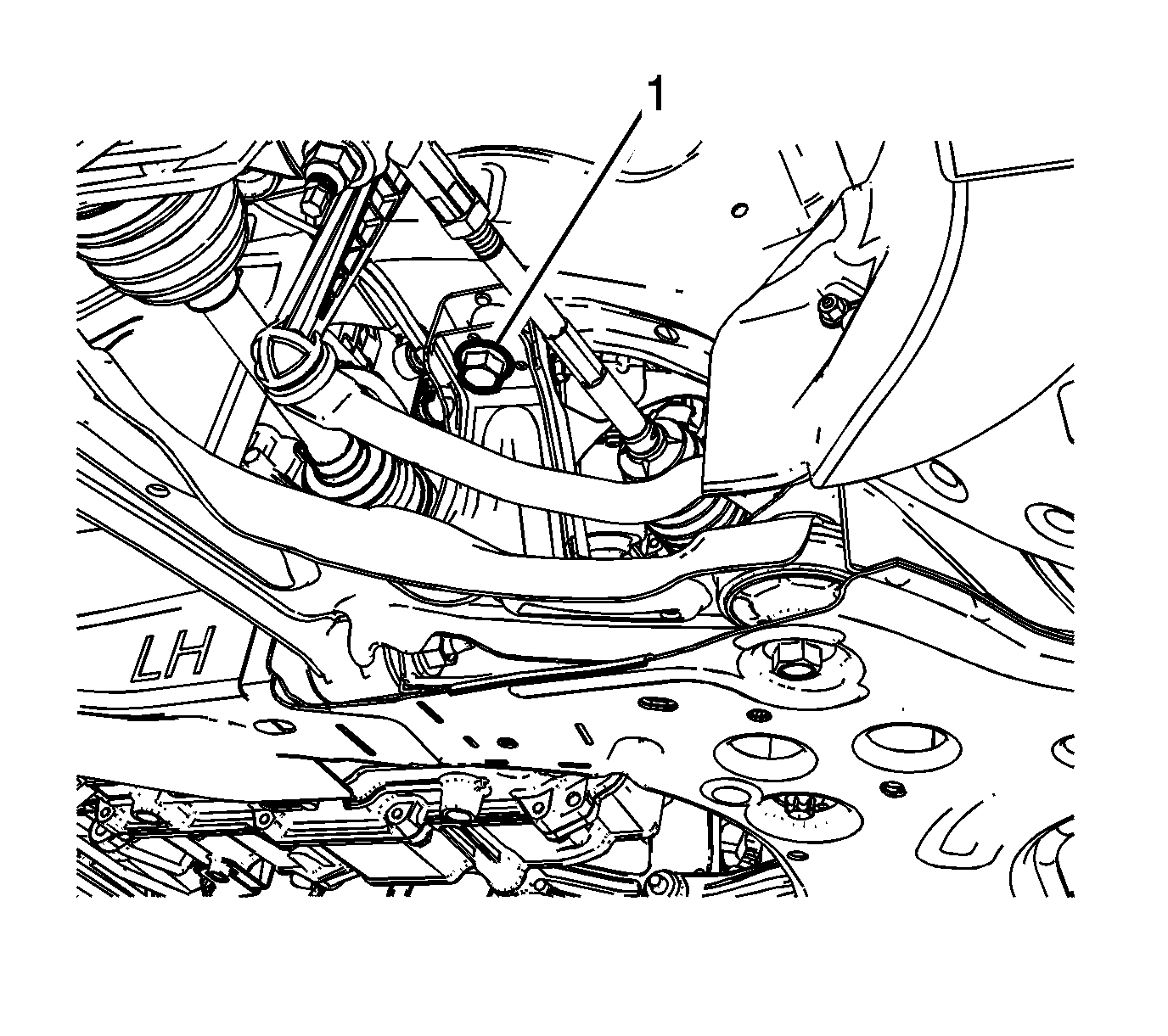
42. Remove the upper frame suspension retaining bolts (1) on both sides.
Pic 21
43. Remove the right side engine mount (1). Refer to Engine Mount Replacement - Right Side See: Engine Mount > Removal and Replacement > Engine Mount Replacement - Right Side.
Pic 22
44. Remove and DISCARD the transmission mount bolts (1) - left side. Refer to Transmission Mount Replacement - Left Side See: Automatic Transmission/Transaxle > Removal and Replacement > Transmission Mount Replacement - Left Side.
45. Disconnect any additional electrical connections as necessary.
46. Raise the vehicle until the powertrain is clear for removal.
Pic 23
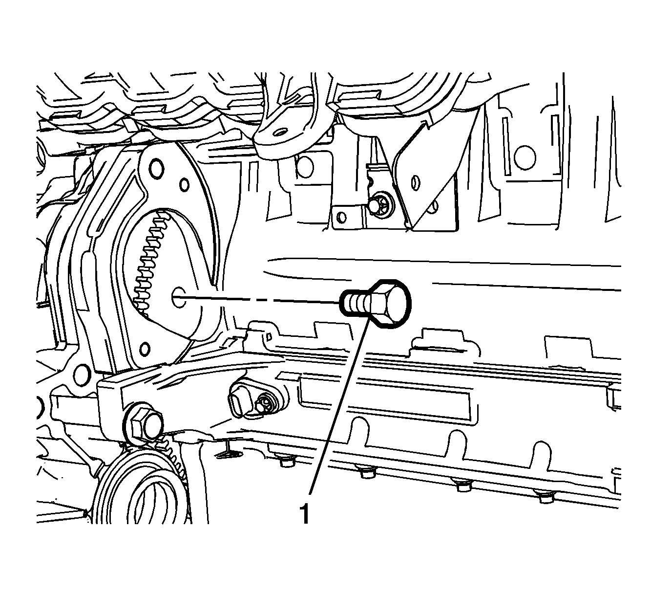
47. If equipped with an automatic transmission, remove the starter. Refer to Starter Replacement (LUV) See: Starter Motor > Removal and Replacement > Starter ReplacementStarter Replacement (2H0) See: Starter Motor > Removal and Replacement > Starter Replacement.
48. Mark the relationship of the flex plate to the torque converter for reassembly.
49. Remove and DISCARD the flex plate to torque converter bolts (1).
Pic 24
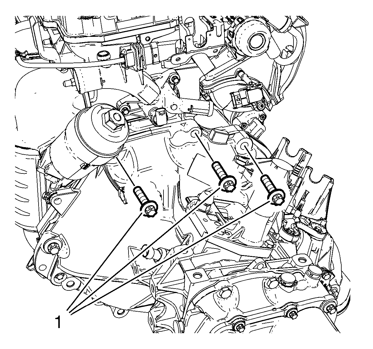
50. If equipped with an automatic transmission, remove the upper transmission to engine bolts (1) and separate the engine and transmission.
Pic 25
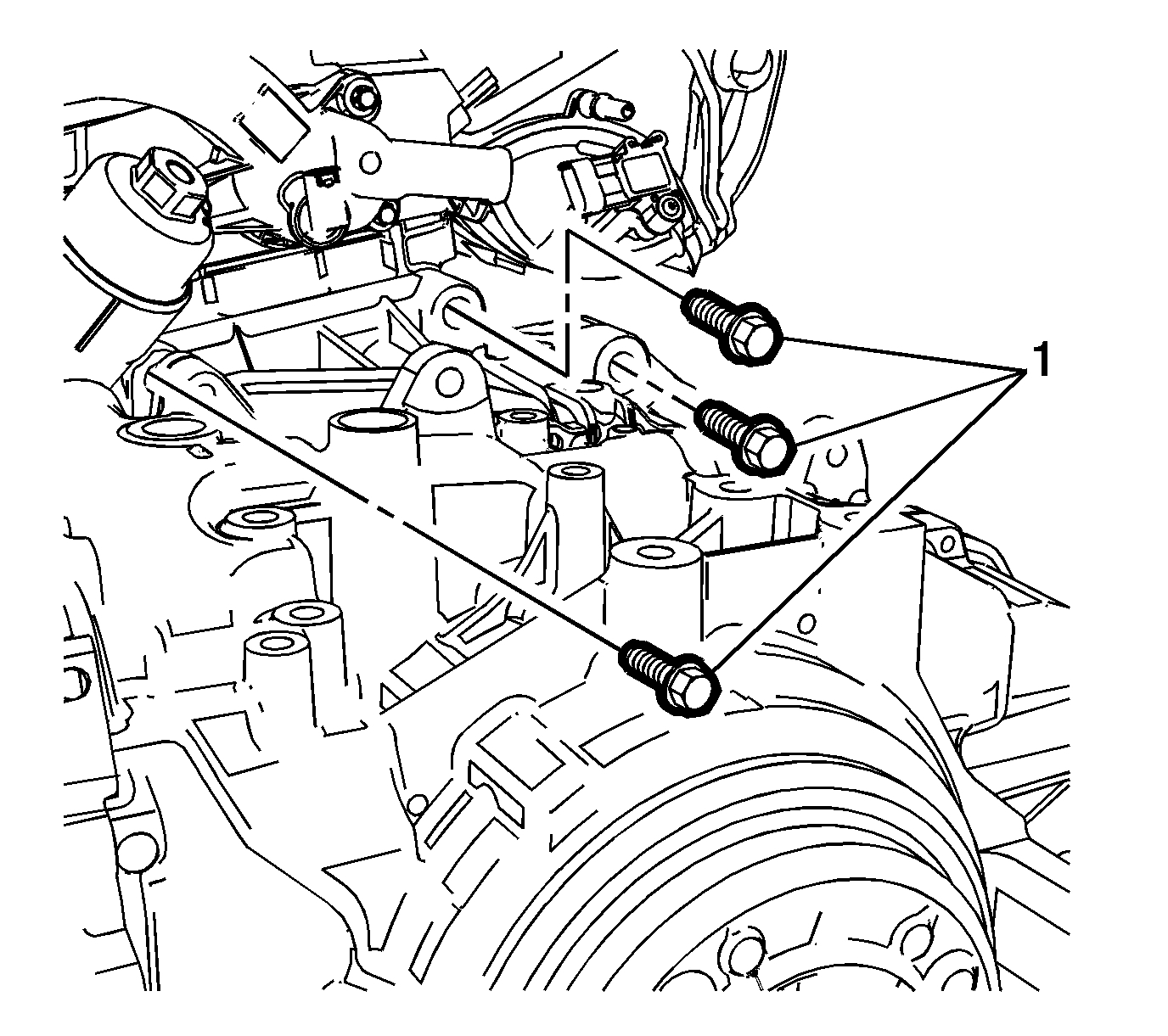
51. If equipped with manual transmission, remove the upper transmission to engine bolts (1). And separate the engine and transmission.
52. Disconnect any electrical connectors as needed.
53. Transfer parts as necessary.
Installation Procedure
1. Install the transmission to the engine.
Pic 26
Caution: Refer to Fastener Caution See: Vehicle > Technician Safety Information > Fastener Caution.
2. If equipped with a manual transmission, install the upper transmission to engine bolts (1) to 60 Nm(44 lb ft).
Pic 27
3. If equipped with automatic transmission, install the upper transmission to engine bolts (1) and tighten to 60 Nm (44 lb ft).
Pic 28
4. If equipped with an automatic transmission, install the torque converter to flex plate bolts (1) and tighten to 60 Nm (44 lb ft).
5. Install the starter. Refer to Starter Replacement (LUV) See: Starter Motor > Removal and Replacement > Starter ReplacementStarter Replacement (2H0) See: Starter Motor > Removal and Replacement > Starter Replacement.
6. Position the powertrain under the vehicle and slowly lower the body onto the powertrain.
Pic 29
Caution: Refer to Torque-to-Yield Fastener Caution See: Timing Components > Technician Safety Information > Torque-to-Yield Fastener Caution.
7. Install the NEW left transmission mount to transmission bolts (1) and tighten to 50 Nm (37 lb ft) plus 70 degrees.
Pic 30
8. Install the right side engine mount (1). Refer to Engine Mount Replacement - Right Side See: Engine Mount > Removal and Replacement > Engine Mount Replacement - Right Side.
9. Connect all previously disconnected electrical connections.
Pic 31
10. Install the frame (3) rear bolts (2) and front bolts (1) and tighten a little bit.
11. Install the frame (3) rear bolts (2) and tighten to 135 Nm (100 lb ft).
12. Install the frame (3) front bolts (1) and tighten to 58 Nm (43 lb ft).
Pic 32
13. Install the upper frame suspension retaining bolts (1) on both sides and tighten to 135 Nm (100 lb ft).
14. Remove the lift table.
Pic 33
15. If equipped with manual transmission, install the lower transmission bolts (1) and tighten to 60 Nm (44 lb ft).
16. Install the lower transmission bolts (2) and tighten 40 Nm (30 lb ft).
17. Install the lower transmission bolt (3) and nut (4) and tighten to 40 Nm (30 lb ft).
Pic 34
18. If equipped with an automatic transmission, install the lower transmission bolts (2, 4) and tighten to 60 Nm (44 lb ft).
19. Install the lower transmission bolts (3) and the lower transmission nut (1) and tighten to 40 Nm (30 lb ft).
20. Install the front exhaust pipe. Refer to Exhaust Front Pipe Replacement (LUV) See: Heat Shield, Exhaust > Removal and Replacement > Exhaust Front Pipe ReplacementExhaust Front Pipe Replacement See: Heat Shield, Exhaust > Removal and Replacement > Exhaust Front Pipe Replacement.
Pic 35
21. Install the wheel drive shafts. Refer to Front Wheel Drive Shaft Replacement - Left Side See: Axle Shaft Assembly > Removal and Replacement > Front Wheel Drive Shaft Replacement - Left Side and Front Wheel Drive Shaft Replacement - Right Side See: Axle Shaft Assembly > Removal and Replacement > Front Wheel Drive Shaft Replacement - Right Side.
Pic 36
22. Connect the evaporative emission pipe (1). Refer to Plastic Collar Quick Connect Fitting Service See: Coolant Line/Hose > Procedures > Plastic Collar Quick Connect Fitting Service.
23. Connect the fuel feed pipe. Refer to Plastic Collar Quick Connect Fitting Service See: Coolant Line/Hose > Procedures > Plastic Collar Quick Connect Fitting Service.
Pic 37
24. Install air conditioning compressor and condenser hose to the refrigerant hose.
25. Install air conditioning compressor and condenser hose nut (1) tighten nut to 22 Nm (16 lb ft).
Pic 38
26. Install the radiator surge tank (2). Refer to Radiator Surge Tank Replacement (LUV, 2H0, LUJ) See: Coolant Reservoir > Removal and Replacement > Radiator Surge Tank Replacement.
27. Connect the fan connector.
Pic 39
28. If equipped with manual transmission, Connect the shift lever and selector lever cable end (1) to the transmission shift lever and selector lever.
29. Connect the shift lever and selector lever cable to the shift lever and selector lever cable bracket.
30. Install the cable retainers (2) to the shift lever and selector lever cable bracket.
Pic 40
31. If equipped with automatic transmission, install the transmission range selector lever cable (2) to the cable bracket.
32. Connect the transmission range selector lever cable terminal (1) to the transmission manual shift lever pin.
33. Adjust the automatic transmission range selector lever cable. Refer to Range Selector Lever Cable Adjustment See: Shift Cable, A/T > Adjustments > Range Selector Lever Cable Adjustment.
34. Connect the heater inlet hose from the heater core. Refer to Heater Inlet Hose Replacement (LUJ, LUV) See: Heater Hose > Removal and Replacement > Heater Inlet Hose ReplacementHeater Inlet Hose Replacement (2H0) See: Heater Hose > Removal and Replacement > Heater Inlet Hose Replacement.
Pic 41
35. Connect the heater outlet hose (2) from the heater core. Refer to Heater Outlet Hose Replacement (2H0) See: Heater Hose > Removal and Replacement > Heater Outlet Hose Replacement (Front)Heater Outlet Hose Replacement (LUJ, LUV) See: Heater Hose > Removal and Replacement > Heater Outlet Hose Replacement (Front)Heater Outlet Hose Replacement (LUJ, LUV Rear) See: Heater Hose > Removal and Replacement > Heater Outlet Hose Replacement (Rear).
Pic 42
36. Install the ground nuts (1) and wiring harness (2).
Pic 43
37. Clip in the wiring harness plugs (1).
Pic 44
38. Install the junction block to the base (3).
39. Install the junction block bolts (2) and tighten to 5 Nm (44 lb in).
40. Install the junction block nut (1) and tighten to 5 Nm (44 lb in).
Pic 45
41. Install the battery positive cable to the battery positive cable junction block and tighten nut (1) to 5 Nm (44 lb in).
42. Connect the body wiring master harness connector (2), to the battery positive cable junction block.
Pic 46
43. Position the positive battery cable (2) to the junction block.
44. Install the positive battery cable nut (1) and tighten to 7 Nm (62 lb in).
Pic 47
45. Install the junction block cover (1).
Pic 48
46. Install the air cleaner assembly (1). Refer to Air Cleaner Assembly Replacement See: Air Cleaner Housing > Removal and Replacement > Air Cleaner Assembly Replacement.
Pic 49
47. Install the lower intermediate steering shaft bolt (1). Refer to Intermediate Steering Shaft Replacement (NJ1) See: Steering Shaft > Removal and Replacement > Intermediate Steering Shaft Replacement (Non-Variable Ratio, Electric)Intermediate Steering Shaft Replacement (N40) See: Steering Shaft > Removal and Replacement > Intermediate Steering Shaft Replacement (Non-Variable Ratio).
48. Install the battery and battery tray. Refer Battery Tray Replacement See: Battery Tray > Removal and Replacement > Battery Tray Replacement.
49. Install the front tire and wheel assembly. Refer to Tire and Wheel Removal and Installation See: Wheels and Tires > Removal and Replacement > Tire and Wheel Removal and Installation.
50. Install the front bumper fascia. Refer to Front Bumper Fascia Replacement (Chevrolet) Front Bumper Fascia Replacement (Buick).
51. Evacuate and charge the refrigerant system. Refer to Refrigerant Recovery and Recharging (R-134a) See: Heating and Air Conditioning > Procedures > Refrigerant Recovery and Recharging (R-134a).
52. Fill the cooling system. Refer to Cooling System Draining and Filling See: Cooling System > Procedures > Cooling System Draining and Filling.
_____________________
Let me know if this helps.
Joe
Images (Click to make bigger)
SPONSORED LINKS
Friday, February 7th, 2020 AT 1:35 PM