Hi and thanks for using 2CarPros.com.
I have to be honest, many things can cause a no start. However, the idea that it is cranking faster or sounds different concerns me. That is usually an indication of a timing issue which could be the result of a broken timing belt. The first thing I would do is check engine compression. If you want to do it yourself, here are directions:
https://www.2carpros.com/articles/how-to-test-engine-compression
If you find low compression, next I would check the timing belt. Here are directions for checking it. This will require some time. NOTE: You listed an engine size that doesn't exist. The attached info is for a 4.7L. If that is incorrect, let me know.
PLEASE NOTE: If the timing belt has failed and broken, this engine is what is known as an interference engine. That means major internal engine damage can result in the event of belt failure.
____________________________
CONVERSION CALCULATOR
1998 Toyota Truck Landcruiser AWD V8-4.7L (2UZ-FE)
Vehicle � Engine, Cooling and Exhaust � Engine � Timing Belt � Testing and Inspection
TESTING AND INSPECTION
INSPECTION
INSPECT TIMING BELT.
NOTICE:
Do not bend, twist or turn the timing belt inside out.
Do not allow the timing belt to come into contact wit oil, water or steam.
Do not utilize timing belt tension when installing or removing the mount bolt of the camshaft timing pulley.
If there are any defects, as shown in the illustrations, check these points:
Premature parting
Check for proper installation.
Check the timing cover gasket for damage and proper installation.
If the belt teeth are cracked or damaged, check to see if either camshaft is locked.
If there is noticeable wear or cracks on the belt face, check to see if there are nicks on the side of the idler pulley lock and water pump.
If there is wear or damage on only one side of the belt, check the belt guide and the alignment of each pulley.
If there is noticeable wear on the belt teeth, check timing cover for damage and for foreign material on the pulley teeth. If necessary, replace the timing belt.
INSPECT IDLER PULLEYS.
Visually check the seal portion of the idler pulley for oil leakage. If leakage is found, replace the idler pulley.
Check that the idler pulley turns smoothly. If necessary, replace the idler pulley.
INSPECT TIMING BELT TENSIONER.
Visually check the seal portion of the tensioner for oil leakage.
HINT: If there is only the faintest trace of oil on the seal on the push rod side, the tensioner is all right.
If leakage is found, replace the tensioner.
Hold the tensioner with both hands and push the push rod strongly as shown to check that it doesn't move. If the push rod moves, replace the tensioner.
NOTICE: Never hold the tensioner push rod facing downward.
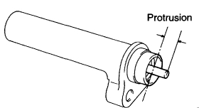
Measure the protrusion of the push rod from the housing end.
Protrusion: 10.5 -11.5 mm (0.413 - 0.453 inch)
If the protrusion is not as specified, replace the tensioner.
________________________________________________
If you find the belt has jumped or broken, here are the directions for removal and replacement. Please keep in mind, I'm not sure what you are able to do, but I figured I would include the directions if you want them. Pictures 6 through 30 are for removal.
CONVERSION CALCULATOR
1998 Toyota Truck Landcruiser AWD V8-4.7L (2UZ-FE)
Vehicle � Engine, Cooling and Exhaust � Engine � Timing Belt � Service and Repair � Timing Belt Removal
TIMING BELT REMOVAL
REMOVAL
REMOVE OIL PAN PROTECTOR.
REMOVE ENGINE UNDER COVER.
DRAIN ENGINE COOLANT.
REMOVE BATTERY CLAMP COVER.
REMOVE INTAKE AIR CONNECTOR.
REMOVE V-BANK COVER.
Remove the fuel return hose from the V-bank cover.
Remove the 2 bolt, 2 cap nuts and V-bank cover.
REMOVE AIR CLEANER AND INTAKE AIR CONNECTOR ASSEMBLY.
REMOVE DRIVE BELT, FAN, FLUID COUPLING AND FAN PULLEY.
Loosen the 4 nuts holding the fluid coupling to the fan bracket.
Remove the generator drive belt.
Remove the 4 nuts, the fan, fluid coupling assembly and fan pulley.
REMOVE RADIATOR ASSEMBLY.
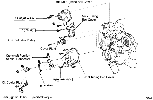
REMOVE DRIVE BELT IDLER PULLEY. Remove the pulley bolt, cover plate and idler pulley.
REMOVE RH NO.3 TIMING BELT COVER. Remove the 3 bolts, nut RH No.3 timing belt cover.
REMOVE LH NO.3 TIMING BELT COVER.
Disconnect the engine wire from the 2 wire clamps.
Remove the 4 bolts and nut.
Disconnect the camshaft position sensor wire from the wire clamp on the LH No.3 timing belt cover.
Disconnect the sensor connector from the connector bracket.
Disconnect the sensor connector.
Remove the wire grommet from the LH No.3 timing belt cover.
Remove the LH No.3 timing belt cover.
Remove the oil cooler pipe and 2 bolts.
REMOVE NO.2 TIMING BELT COVER.
Remove the 2 bolts and No.2 timing belt cover.
DISCONNECT A/C COMPRESSOR FROM ENGINE.
REMOVE FAN BRACKET.
Remove the 2 bolts, 2 nuts and fan bracket.
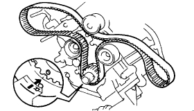
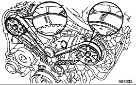
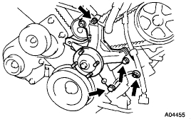
IF RE-USING TIMING BELT, CHECK INSTALLATION MARKS ON TIMING BELT. Check that there are 3 installation marks on the timing belt by turning the crankshaft pulley as shown in the illustration.
HINT: If the installation marks have disappeared, place a new installation mark on the timing belt before removing each part.
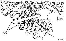
LOOSEN CRANKSHAFT PULLEY BOLT.
Using Special Service Tool (SST) , loosen the pulley bolt.
SST 09213 - 70010 (90105 - 08076), 09330 - 00021
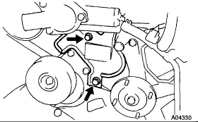
SET NO.1 CYLINDER TO APPROXIMATELY 50°ATDC/COMPRESSION.
Turn the crankshaft pulley and align its groove with timing mark "0" of the No.1 timing belt cover.
Check that the timing marks of the camshaft timing pulleys and timing belt rear plates aligned. If not, turn the crankshaft 1 revolution (360°).
Turn the crankshaft pulley approximately 50°clockwise, and put the timing mark of the crankshaft pulley in line with the centers of the crankshaft pulley bolt and the idler pulley bolt.
NOTICE: If the timing belt is disengaged, having the crankshaft pulley at the wrong angle can cause the piston head and valve head to come into contact with each other when you remove the camshaft timing pulley (step 19), causing damage. So always set the crankshaft pulley at the correct angle.
Remove the crankshaft pulley bolt.
NOTICE: Do not turn the crankshaft pulley.
REMOVE TIMING BELT TENSIONER.
HINT:
When re-using timing belt: If the installation marks have disappeared, before remove the timing belt, place 2 new installation marks on the timing belt to match the timing marks of the camshaft timing pulleys.
When replacing timing belt tensioner only: To avoid meshing of the timing pulley and timing belt, secure one of them with string. And place matchmarks on the timing belt and RH camshaft timing pulley.
Alternately loosen the 2 bolts, and remove them, the belt tensioner and dust boot.
DISCONNECT TIMING BELT FROM CAMSHAFT TIMING PULLEYS.
Using SST, loosen the tension spring between the LH and RH camshaft timing pulleys by slightly turning the LH camshaft timing pulley clockwise. SST 09960 - 10010 (09962 - 01000, 09963 - 01000)
Disconnect the timing belt from the camshaft timing pulleys.
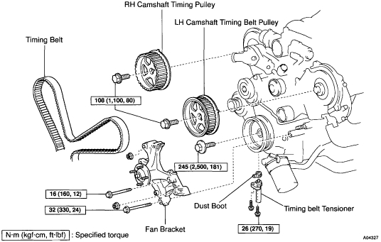
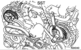
REMOVE CAMSHAFT TIMING PULLEYS.
Using SST, remove the bolt and timing pulley. Remove the timing pulleys.
SST 09960-10010 (09962-01000, 09963 - 01000)
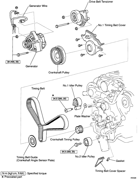
REMOVE GENERATOR.
REMOVE DRIVE BELT TENSIONER. Remove the bolt, 2 nuts and belt tensioner.
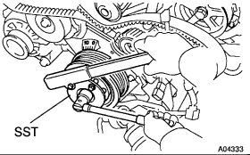
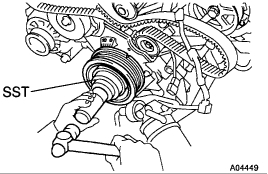
REMOVE CRANKSHAFT PULLEY.
Using SST, remove the crankshaft pulley.
SST 09950 - 50010 (09951 - 05010, 09952 - 05010, 09953 - 05010, 09953 - 05020, 09954 - 05020)
NOTICE: Do not turn the crankshaft pulley.
REMOVE NO.1 TIMING BELT COVER. Remove the 4 bolts, timing belt cover.
REMOVE TIMING BELT GUIDE.
REMOVE TIMING BELT COVER SPACER.
REMOVE TIMING BELT.
HINT: If re-using the belt and the installation mark has disappeared from it, place a new installation mark on the timing belt to the match the dot mark of the crankshaft timing pulley.
REMOVE NO.1 IDLER PULLEY AND NO.2 IDLER PULLEY.
Using a 10 mm hexagon wrench, remove the bolt, No.1 idler pulley and plate washer.
Remove the bolt and No.2 idler pulley.
REMOVE CRANKSHAFT TIMING PULLEY.
Using SST, remove the timing pulley.
SST 09950 - 50010 (09951 - 05010, 09952 - 05010, 09953 - 05010, 09953 - 05020, 09954 - 05010)
NOTICE: Do not turn the timing pulley.
____________________________________________________________
Directions for replacement. Remaining pics correlate with these directions.
CONVERSION CALCULATOR
1998 Toyota Truck Landcruiser AWD V8-4.7L (2UZ-FE)
Vehicle � Engine, Cooling and Exhaust � Engine � Timing Belt � Service and Repair � Timing Belt Installation
TIMING BELT INSTALLATION
INSTALLATION
INSTALL CRANKSHAFT TIMING PULLEY.
Align the timing pulley set key with the key groove of the pulley.
Using Special Service Tool (SST) and a hammer, tap in the timing pulley, facing the flange side inward. SST 09223 - 46011
INSTALL NO.1 IDLER PULLEY AND NO.2 IDLER PULLEY.
Apply adhesive 2 or 3 threads of the pivot bolt. Adhesive: Part No. 08833 - 00080, THREE BOND 1344, LOCTITE 242 or equivalent
Using a 10 mm hexagon wrench, install the plate washer and No.1 idler pulley with the pivot bolt.
Torque: 34.5 Nm (25 ft. lbs.)
Install the No.2 idler pulley with the bolt.
Torque: 34.5 Nm (25 ft. lbs.)
Check that the No.1 and No.2 idler pulley moves smoothly.
TEMPORARILY INSTALL TIMING BELT.
NOTICE: The engine should be cold.
Remove any oil or water on the crankshaft pulley, oil pump pulley, water pump pulley, No.1 idler pulley and No.2 idler pulley, and keep them clean.
NOTICE: Only wipe the pulleys; do not use any cleansing agent.
Align the installation mark on the timing belt with the timing mark of the crankshaft timing pulley.
Install the timing belt on the crankshaft timing pulley, No.1 idler pulley and No.2 idler pulley.
INSTALL TIMING BELT COVER SPACER.
Install the gasket to the cover spacer.
Install the cover spacer.
INSTALL TIMING BELT GUIDE. Install the belt guide, facing the cup side outward.
INSTALL NO.1 TIMING BELT COVER. Install the timing belt cover with the 4 bolts.
INSTALL CRANKSHAFT PULLEY.
Align the pulley set key with the key groove of the crankshaft pulley.
Using SST and a hammer, tap in the crankshaft pulley. SST 09223 - 46011
INSTALL DRIVE BELT TENSIONER. Install the belt tensioner with the bolt and 2 nuts.
Torque: 16 Nm (12 ft. lbs.)
HINT: Use a bolt 106 mm (4.18 inch) in length.
INSTALL GENERATOR.
CHECK CRANKSHAFT PULLEY POSITION. Check that the timing mark of the crankshaft pulley is aligned with the centers of the crankshaft pulley and the idler pulley bolt.
INSTALL RH, LH CAMSHAFT TIMING PULLEYS.
Align the camshaft knock pin with the knock pin grove of the timing pulley, and slide on the timing pulley.
Using SST, install the pulley bolt. SST 09960 - 10010 (09962 - 01000, 09963 - 01000)
Torque: 108 Nm (80 ft. lbs.)
CONNECT TIMING BELT TO LH CAMSHAFT TIMING PULLEY.
Remove any oil or water on the LH camshaft timing pulley, and keep it clean.
NOTICE: Only wipe the pulleys; do not use any cleansing agent.
Turn the LH camshaft timing pulley. Align the installation mark on the timing belt with the timing mark of the camshaft timing pulley, and hang the timing belt on the LH camshaft timing pulley.
Turn the LH camshaft timing pulley counterclockwise until there is tension between the crankshaft timing pulley and LH camshaft timing pulley.
CONNECT TIMING BELT TO RH CAMSHAFT TIMING PULLEY.
Remove any oil or water on the RH camshaft timing pulley and water pump pulley, and keep them clean.
NOTICE: Only wipe the pulleys; do not use any cleansing agent.
Turn the RH camshaft timing pulley. Align the installation mark on the timing belt with the timing mark of the camshaft timing pulley, and hang the timing belt on the RH camshaft timing pulley.
SET TIMING BELT TENSIONER.
Using a press, slowly press in the push rod using 981 - 9,807 N (220 - 2,205 lbs.) of pressure.
Align the holes of the push rod and housing, pass a 1.27 mm hexagon wrench through the holes to keep the setting position of the push rod.
Release the press.
Install the dust boot to the belt tensioner.
INSTALL TIMING BELT TENSIONER.
Temporarily install the belt tensioner with the 2 bolts.
Alternately tighten the 2 bolts.
Torque: 26 Nm (19 ft. lbs.)
Using pliers, remove the 1.27 mm hexagon wrench from the belt tensioner.
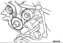
CHECK VALVE TIMING.
Temporarily install the crankshaft pulley bolt.
Slowly turn the crankshaft pulley 2 revolutions from Top Dead Center (TDC) to TDC.
NOTICE: Always turn the crankshaft pulley clockwise.
Check that each pulley aligns with the timing marks as shown in the illustration. If the timing marks do not align, remove the timing belt and reinstall it.
TIGHTEN CRANKSHAFT PULLEY BOLT.
Using SST, install the pulley bolt.
SST 09213 - 54015 (90119 - 08216), 09330 - 00021
Torque: 245 Nm (181 ft. lbs.)
INSTALL FAN BRACKET.
Install the fan bracket with the 2 bolts and 2 nuts.
Torque:
12 mm head: 16 Nm (12 ft. lbs.)
14 mm head: 32 Nm (24 ft. lbs.)
HINT: Each bolt length is indicated in the illustration.
Bolt Length:
106 mm (4.17 inch) for 12mm head (A)
114 mm (4.49 inch) for 14 mm head (B)
INSTALL A/C COMPRESSOR.
INSTALL NO.2 TIMING BELT COVER.
Install the No.2 timing belt cover with the 2 bolts.
Torque: 16 Nm (12 ft. lbs.)
INSTALL RH NO.3 TIMING BELT COVER.
Fit the RH No.3 timing belt cover, matching it with the fan bracket.
Install the RH No.3 timing belt cover with the 3 bolts and nut.
Torque: 7.5 Nm (66 inch lbs.)
INSTALL LH NO.3 TIMING BELT COVER.
Install the oil cooler pipe and bolt.
Run the camshaft position sensor wire through the LH No.3 timing belt cover hole.
Fit the LH No.3 timing belt cover, matching it with the fan bracket.
Install the LH No.3 timing belt cover with the 4 bolts and nut.
Torque: 7.5 Nm (66 inch lbs.)
Install the wire grommet to the LH No.3 timing belt cover.
Install the sensor connector to the connector bracket.
Connect the sensor connector.
Install the sensor wire to the wire clamp on the LH No.3 timing belt cover.
Install the engine wire to the 2 wire clamps on the LH No.3 timing belt cover.
INSTALL DRIVE BELT IDLER PULLEY. Install the idler pulley and cover plate with the bolt.
Torque: 37 Nm (27 ft. lbs.)
INSTALL RADIATOR ASSEMBLY.
INSTALL FAN PULLEY, FAN, FLUID COUPLING AND DRIVE BELT.
Temporarily install the fan pulley, the fan, fluid coupling assembly with the 4 nuts.
Install the generator drive belt.
Tighten the 4 nuts holding the fluid coupling to the fan bracket.
Torque: 21 Nm (16 ft. lbs.)
INSTALL AIR CLEANER AND INTAKE AIR CONNECTOR ASSEMBLY.
INSTALL V-BANK COVER.
FILL WITH ENGINE COOLANT.
START ENGINE AND CHECK FOR LEAKS.
RECHECK ENGINE COOLANT LEVEL.
INSTALL INTAKE AIR CONNECTOR.
INSTALL BATTERY CLAMP COVER.
INSTALL ENGINE UNDER COVER.
INSTALL OIL PAN PROTECTOR.
_____________________________________________
As you can see, it is not an easy job. Again, this is an interference engine. If the belt broke, the cylinder heads need removed to check for damage to the valves and the pistons. In most cases, it is cheaper to find a good used engine and replace the existing one.
I will keep my fingers crossed that is not the issue. Please update me on what you find or if you have other questions.
Take care and good luck,
Joe
Images (Click to make bigger)
SPONSORED LINKS
Thursday, June 21st, 2018 AT 9:04 PM