ECM/PCM pin #48

Tiny
RVMAN350
  • MEMBER
  • 1998 PONTIAC GRAND PRIX
  • 3.8L
  • V6
  • 2WD
  • AUTOMATIC
  • 159,000 MILES
I just rebuilt my 3800 v-6 bottom up new everything i/e bearings, rings, heads, performance cam, double roller chain, new lifters, pushrods new performance fuel injectors and coil packs, plus lots more. I had also purchased a tuned ECM/PCM from the same company so they had all of my info. I had everything wired except the ECM/PCM cranking engine with remote starter switch to build oil pressure everything good so far disconnected the battery to install and hook up ECM/PCM went to hook up the battery and immediately saw smoke by the ECM/PCM removed battery, cable checked all wiring for pinch or shorted wires none found. I went to hook up battery again same thing, looked closer at the ECM/PCM and noticed that the insulation on the red with black stripe wire going to pin #48 on the ECM/PCM was melted any clues?
Thursday, February 25th, 2021 AT 4:15 PM

4 Replies

Tiny
ASEMASTER6371
  • MECHANIC
  • 52,797 POSTS
Good evening,

Was there an issue with the old ECM?

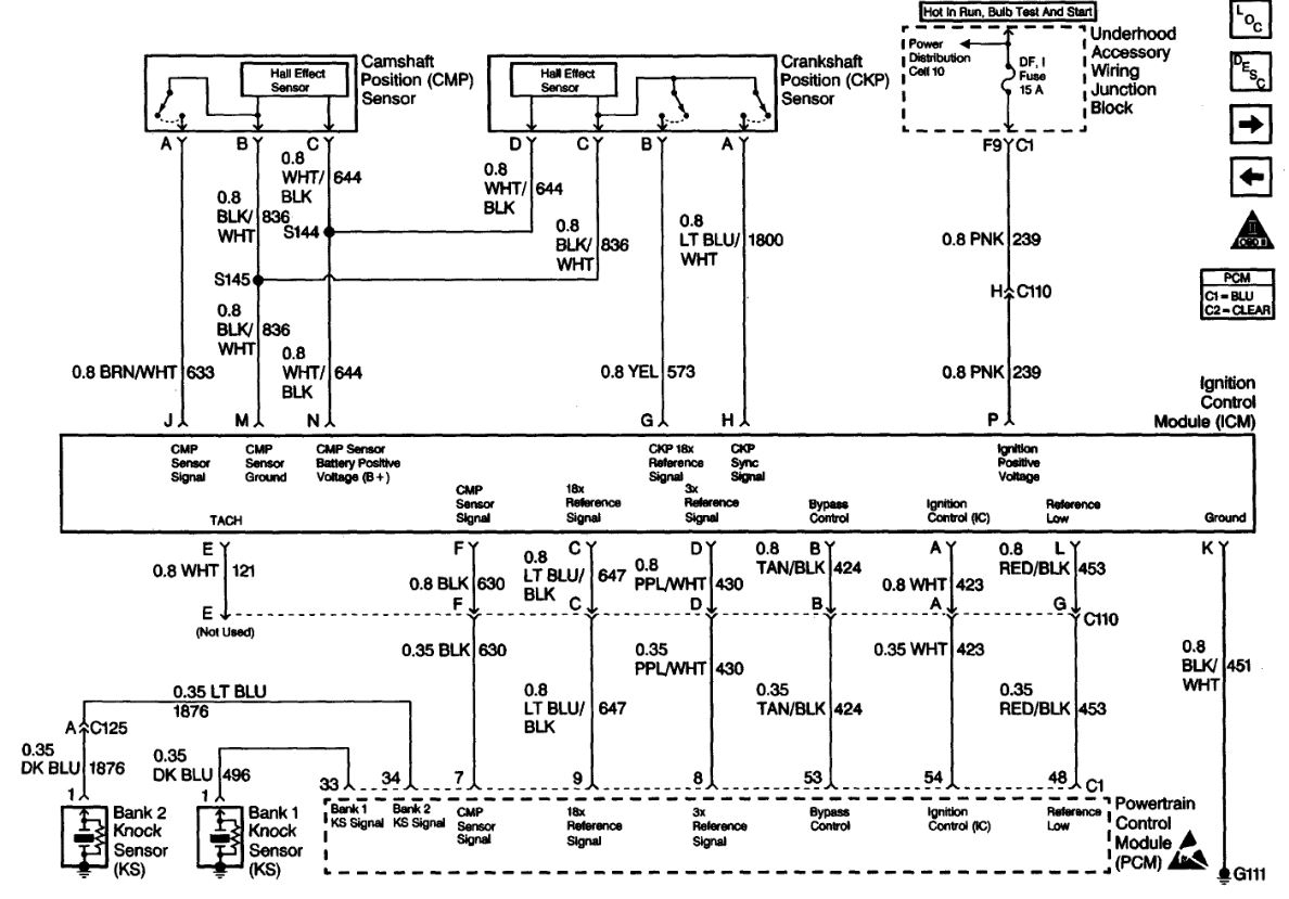
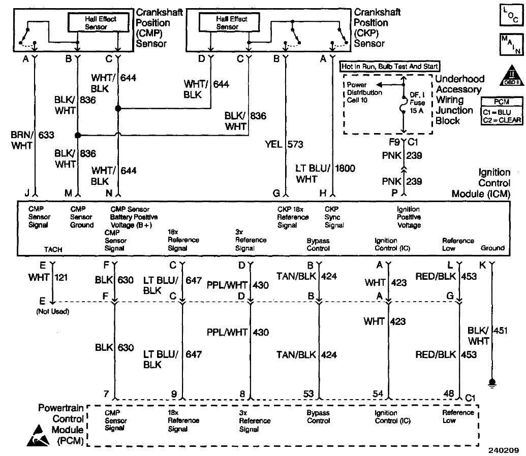
Pin 48 is a reference from the ignition module.

I attached a picture for you. It sounds like your new ECM is no good.

Roy

PCM REPLACEMENT / PROGRAMMING PROCEDURE

CAUTIONS:
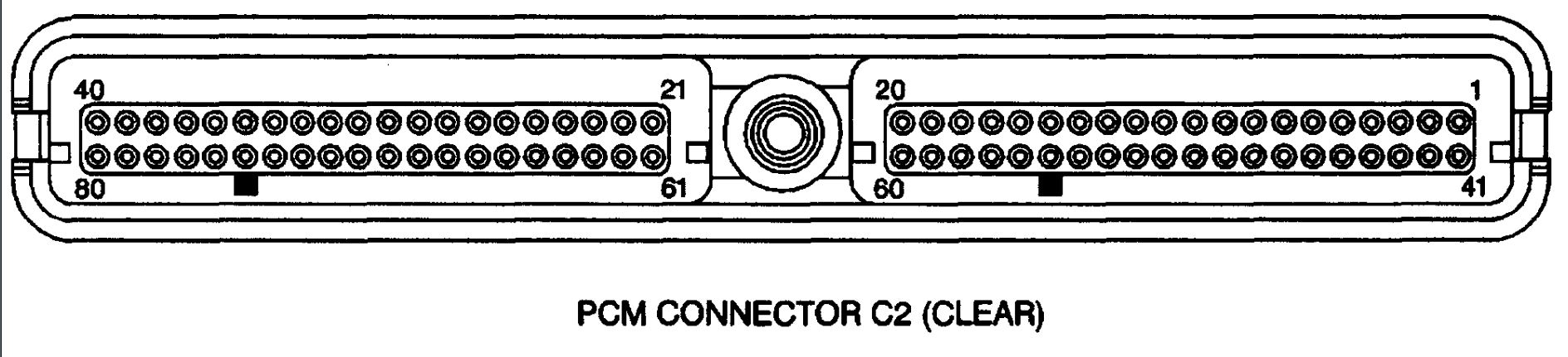
- In order to prevent possible Electrostatic Discharge damage to the PCM, Do Not touch the connector pins or the soldered components on the circuit board.
- In order to prevent internal PCM damage, leave the ignition OFF when installing or removing the PCM connectors and disconnecting or reconnecting the power to the PCM (battery cable, PCM pigtail, PCM fuse, jumper cables, etc.).

NOTES:
- Service of the PCM should normally consist of either replacement of the PCM or EEPROM programming. If the diagnostic procedures call for the PCM to be replaced, PCM should be checked first to see if it is the correct part. If it is, remove the faulty PCM and install the new service PCM.
- When replacing the production PCM with a service PCM, it is important to transfer the broadcast code and production PCM number to the service PCM label. Do not record on PCM cover. This will allow positive identification of PCM parts throughout the service life of the vehicle.
- THE SERVICE PCM EEPROM WILL NOT BE PROGRAMMED. DTC PO6O2 indicates the EEPROM is not programmed or has malfunctioned.

REMOVAL PROCEDURE
1. Disconnect the negative battery cable.
2. Remove the left strut brace.
3. Remove the air cleaner housing cover and the PCM from the housing assembly.
4. Disconnect the harness connectors from PCM.
5. Remove the PCM from the engine compartment.

INSTALLATION PROCEDURE
1. Install the connectors to the PCM.
2. Install the PCM into the air cleaner housing cover.
3. Install the air cleaner housing cover.
4. Connect the negative battery cable.
5. If a new PCM is being Installed, program the EEPROM. See: Engine Control Module > Procedures > EEPROM Programming
6. The PCM will need to learn the crankshaft variation. Refer to CKP System Variation Learn Procedure. See: Engine Control Module > Procedures > Crankshaft Position System Variation Learn Procedure
Was this
answer
helpful?
Yes
No
+1
Thursday, February 25th, 2021 AT 4:53 PM
Tiny
STEVE W.
  • MECHANIC
  • 13,015 POSTS
Pin 48 is the low reference (module to module ground) to the ignition module. I would grab a VOM and measure the pin on the ECM and then check the same wire at the ignition module. I suspect you will find there is voltage on the coil side. Check the ground for the coil packs and if you have the old one connect it up and check it for the same issue. Could be that the coil pack itself is defective. If pin 48 still shows a ground when you test it compared to other grounds the ECM should still be okay.
Was this
answer
helpful?
Yes
No
+1
Thursday, February 25th, 2021 AT 6:08 PM
Tiny
RVMAN350
  • MEMBER
  • 7 POSTS
  • 1998 PONTIAC GRAND PRIX
  • 3.8L
  • V6
  • 2WD
  • AUTOMATIC
  • 150,000 MILES
I found a pinout for a ECU but it is not clear if you are showing the ECU or the harness and which side of the harness that I am looking at. Can you clear that up? Thanks
Was this
answer
helpful?
Yes
No
Thursday, March 11th, 2021 AT 3:36 PM (Merged)
Tiny
STEVE W.
  • MECHANIC
  • 13,015 POSTS
Perhaps these will help. They are the various wiring diagrams that connect to the PCM. The C1 connector is Blue while C2 is "Clear" aka dirty white normally. These are both looking at the face of the connector on the harness.
The others are the wires and what they control from the PCM.
Was this
answer
helpful?
Yes
No
+1
Thursday, March 11th, 2021 AT 3:36 PM (Merged)

Please login or register to post a reply.

Sponsored links