Installation (with mechanical tension-er)
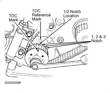
1. Set crankshaft sprocket to TDC by aligning sprocket TDC mark with TDC reference mark arrow on oil pump housing, then back off to three notches before TDC.
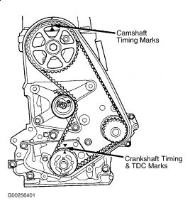
2. Set camshaft to TDC by aligning mark on sprocket with arrow on rear of timing belt cover. Move crankshaft to half notch mark before TDC for belt installation. Install timing belt starting at crankshaft sprocket, then around water pump sprocket, and then camshaft sprocket, and finally around timing belt tension er pulley.
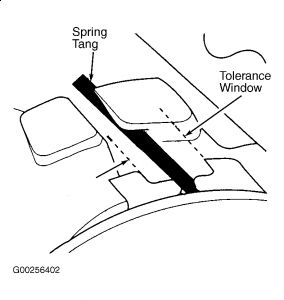
3. Move crankshaft sprocket to TDC to take up belt slack. Install a 6-mm Allen wrench into hexagon opening of top plate tension-er pulley. Rotate tension-er counterclockwise with 6-mm Allen wrench. The tension-er pulley will move against timing belt and tension-er setting notch will eventually start to move clockwise. Watching movement of notch, continue rotating tension-er counterclockwise until the setting notch is aligned with spring tang. Hold tension-er setting notch aligned with spring tang, and tighten tension-er bolts to specification.
4. Remove Allen wrench from timing belt tension-er pulley. Rotate crankshaft clockwise 2 revolutions. Check alignment of camshaft and crankshaft timing marks. Also, check if spring tang is within tolerance window. If timing marks align and spring tang is within specification, go to next step. If timing marks do not align or if spring tang is not within specification, repeat step 3 .
5. Install front timing belt cover. Install engine mount bracket and power steering pump. Install right engine mount and remove jack from under engine. Install and adjust upper and lower engine torque struts. Install crankshaft damper, and tighten bolt to specification.
6. Raise vehicle on hoist. Install right inner splash shield. Lower vehicle. Install accessory drive belts. Adjust drive belts to proper tension.
7. Connect scan tool to Data Link Connector (DLC), located under lower left edge of instrument panel. Turn ignition on. Perform cam/crank relearn procedure by accessing engine diagnostics. Select miscellaneous, then select relearn cam crank and follow directions on scan tool screen.
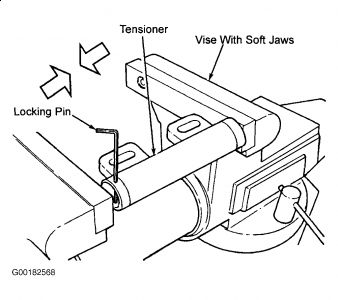
Note: When hydraulic tension-er is removed from engine, it is necessary to compress plunger into tension-er body.
Installation (with hydraulic tension-er)
1. Place tension-er in soft-jawed vise and slowly compress plunger. When plunger is compressed into tension-er body, install a 5/64" (1.9 mm) hex wrench or locking pin through body and plunger to hold plunger in place until tension-er is installed.
2. Set crankshaft sprocket to TDC by aligning sprocket TDC mark with TDC reference mark arrow on oil pump housing, then back off to three notches before TDC.
3. Set camshaft to TDC by aligning mark on sprocket with arrow on rear of timing belt cover. Move crankshaft to half notch mark before TDC for belt installation. Install timing belt starting at crankshaft sprocket, then around water pump sprocket, and then camshaft sprocket, and finally around timing belt tension-er pulley.
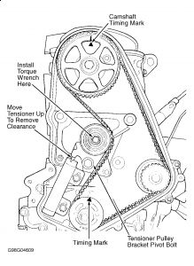
4. Move crankshaft sprocket to TDC to take up belt slack. Install tension-er to block, but do not final tighten bolts. Using a torque wrench on tension-er pulley, apply 21 ft. lbs. (28 N.m) of torque in clockwise direction. With torque applied to tension-er pulley, move the tension-er up against the tension-er pulley bracket. Final tighten tension-er bolts to specification.
5. Pull tension-er plunger locking pin. Pre-tension is correct when pin can be removed and installed. Rotate crankshaft two revolutions. Check alignment of the timing marks. Check belt tension by installing pin into tension-er housing. If pin cannot be reinstalled, repeat tensioning procedure.
6. Install front timing belt cover. Install engine mount bracket and power steering pump. Install right engine mount, and remove jack from under engine. Install and adjust upper and lower engine torque struts. Install crankshaft damper, and tighten bolt to specification.
7. Raise vehicle on hoist. Install right inner splash shield. Lower vehicle. Install accessory drive belts. Adjust drive belts to proper tension.
8. Connect scan tool to data link connector (DLC), located under lower left edge of instrument panel. Turn ignition on. Perform cam/crank relearn procedure by accessing engine diagnostics. Select miscellaneous, then select relearn cam crank and follow directions on scan tool screen.


Mar 14, 2009 at 7:13 PM