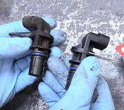
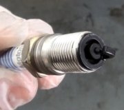
Ive never worked on this particular model, but here are a few things I found about your truck.
1982---84 Models
The Glow Plug Control System - Consists of a thermal controller, a glow plug relay, 6 volt glow plugs and a glow plug warning lamp.
The Thermal Controller - Mounted in the water passage at the rear of the engine controls glow plug ooperation using thermostatic elements within the controller which open or close the ground circuit to the glow plug relay as necessary.
The Glow Plug Relay - Located on the left inner fender panel, provides current to the glow plugs as long as the thermal controller completes the ground circuit.
The 6 Volt Glow Plugs--Used in This 12 Volt System - Are pulsed ON and OFF by the glow plug relay in response to messages received by the controller to prevent damage to the glow plugs.
The Glow Plug Warning Lamp - Mounted in the instrument cluster, and wired across the glow plugs, illuminateds whenever the glow plugs are heating.
Cold Starting
Initially, during cold starting, the glow plugs are activated continuously for 71/2---9 seconds at 0°F.
Engine Warm-up
The glow plugs then pulse on and off at a rate determined by the thermal characteristics of the controller, to provide stable engine warm-up.
As the engine warms up the controller turns off all current to the relay, de-energizing the glow plugs.
In Addition
The controller is capable of varying glow plug operation as needed to allow proper operation during cold starting when little or no heating is required.
In the Event of Controller Failure
A circuit breaker within the controller opens and current to the glow plugs is cut off in the event of controller failure--as in the case of prolonged preheat.
To test the thermal controller,
Disconnect electrical connector from thermal controller.
Measure resistance between controller terminals using high impedance, digital ohmmeter set on 200 ohms scale.
Resistance should be as follows:
Pins 2 to 3.0.40---0.75 ohms
Pins 4 to 5.24---30 ohms
Pins 1 to 5.117---143 ohms
Pins 2 to 6. Continuity (0) ohms
If resistance values are not as specified, controller is defective.
If resistance values are within specifications, reconnect electrical connector and observe controller operation with ignition key in on position and engine stopped.
If controller cycles more than one time, controller is satisfactory.
If controller cycles only once, check for a short or open in harness as outlined in ``System Diagnosis.''
If all other components are satisfactory, but controller cycles only once in step 5, replace controller and recheck system operation.
SPONSORED LINKS
Monday, January 1st, 2007 AT 6:41 PM


