Power windows driver side not working

Tiny
BARRETTGR
  • MEMBER
  • 2001 CHEVROLET SUBURBAN
  • V8
  • 2WD
  • AUTOMATIC
  • 140,000 MILES
My driver side power windows stopped working. The LR all together. The LF will work for about 10 seconds when I first turn on the key and then it stops. Turn off the key and back on again and it will work for another 10 seconds.
Friday, March 19th, 2010 AT 3:51 PM

16 Replies

Tiny
CARADIODOC
  • MECHANIC
  • 33,750 POSTS
There is an over-current self-resetting circuit breaker built into the motors. They cause more trouble than the circuits they protect. I've seen used car lot mechanics take the motors apart and bypass the circuit breakers with a piece of wire, and the motors work like new. I would never do this myself for liability reasons, but it might help to know that power window motors were around for decades that didn't have these circuit breakers in them. Use your judgement since it's your own vehicle.

The proper repair is to replace the motors, and have the same problem in a few years.
Caradiodoc
Was this
answer
helpful?
Yes
No
Friday, March 19th, 2010 AT 6:36 PM
Tiny
BARRETTGR
  • MEMBER
  • 7 POSTS
I hear you. The issue with your diagnose is that I'm not getting power to the motor. When the window fails I checked the connector at the motor and no power. So it can't be the motor as it is not getting any voltage. I'm tempted to rig up something to power the motor directly but the terminals are not easy to get to.
Was this
answer
helpful?
Yes
No
+1
Saturday, March 20th, 2010 AT 7:41 AM
Tiny
CARADIODOC
  • MECHANIC
  • 33,750 POSTS
Ok. I thought the 10 seconds thing was the dead giveaway, but if there's no voltage even getting to the motor, have you checked the wiring between the driver's door hinges?

Your truck is new enough that there might be a Body Computer involved with running the power windows, but regardless, if the 12 volt power wire is broken, none of the windows would work from the any switches. Each door has it's own 12 volt feed wire that comes from the driver's master lockout switch so if that feed wire was broken, only the driver's window would still work. If the ground wire was broken, none of the windows would work because all of them go back through the released driver's switch assembly, then to ground through the ground wire in the driver's door.

To have just one or two windows not work would seem to eliminate broken wires as the cause. Next, I would head to the switch assembly. By the way, are you using a test light or a dc voltmeter? If you are grounding it to the door, you might be getting inaccurate readings. Try to find a nice shiny ground bolt under the dash if you can. Sometimes the door striker works too.

If you have an ohm meter, when no window switches are pressed, both motor wires must read continuity to ground. Unplug the connector because one open circuit can read to ground by going through the motor. If either wire reads open, there is either a break in the wire back to the switch, (rather unlikely), or an open / burned switch contact. I know it can be hard to figure out which wire is which terminal on the switch, so you might have better luck looking at the rear window first. That switch should only have five wires. (I have to do this from memory of Chryslers which are very similar). One wire will have 12 volts, if the master cutout switch is on in the driver's door. Disregard that one. The other four must all read continuity to ground. There are two circuits, one for each motor wire. Each wire goes from the motor, through the LR switch, LR door hinges, through the LF door hinges, through the driver's switch assembly, through the ground wire between the door hinges, and is bolted to the body.

At either switch, pressing it first opens the ground path to one wire, then the contact moves over to touch the 12 volt contact. If you measure voltages at the motor, you will have 0 volts on both wires until you press either switch, then you will have voltage on one wire or the other, depending on the direction the motor should run.

Try making a few of these measurements, then holler back with your findings.

Caradiodoc
Was this
answer
helpful?
Yes
No
Saturday, March 20th, 2010 AT 5:56 PM
Tiny
BARRETTGR
  • MEMBER
  • 7 POSTS
I have continuity from the motor plug to ground and also to the switch. Looks like no broken wires. 0 volts when I activate the switch.

Using common sense (didn't work) I bought a new switch when there was no voltage. Well that didn't change a thing.
Was this
answer
helpful?
Yes
No
+1
Sunday, March 21st, 2010 AT 4:56 PM
Tiny
CARADIODOC
  • MECHANIC
  • 33,750 POSTS
Something doesn't make sense. To verify, both right side windows work from the driver's switch, right? That says battery voltage is getting to the switch assembly. And to double-check, both motor wires read continuity to ground with the connector unplugged?

If that sounds right, find the 12 volts on the feed wire on the driver's switch. You should have it on just one wire when no switch is pressed. Next, there should be 12 volts on that wire AND one other wire in the switch connector when you press a switch. From there, follow that second wire to the motor. It sounds like the voltage is getting lost somewhere along that line.

One other thing to consider; if you're using a voltmeter, it will detect 12 volts if there is nothing more than a carbon track where a wire burned open. That carbon track is such high resistance that no current can get through to run the motor, or even a test light. If this is what is happening, you will see 12 volts on the supply wire, (or any test point), but it will go to 0 volts when you activate the circuit by pressing the switch. Alternately, where you measure 12 volts with the meter you will find a test light does not light up. All this means is to believe your voltmeter, verify all readings by taking a second one while pressing the switch.

Caradiodoc
Was this
answer
helpful?
Yes
No
Sunday, March 21st, 2010 AT 8:31 PM
Tiny
BARRETTGR
  • MEMBER
  • 7 POSTS
I have 12 volts on two orange wires in the LF main switch. 0 volts to any of the motor wires (blue and brown) when the switch is depressed. Also 0 volts to any wire in the LR switch with or without the bypass on in the LF switch.

The right side windows are both normal. 12 volts to green on RR switch and when switch depressed 12 volts to Blue.

My guess is there should be another power source to that LF switch to run the left side since the right side works fine.
Was this
answer
helpful?
Yes
No
Monday, March 22nd, 2010 AT 8:10 AM
Tiny
CARADIODOC
  • MECHANIC
  • 33,750 POSTS
I'm trying to find a wiring diagram, but in the meantime, unless there is a Body Computer involved here, we are overlooking something simple. Answer me these questions so I can figure out if this circuit is similar to Chrysler's.

Turn the driver's master switch off, then try the passenger windows. They should still work from the driver's switch but not from the passenger switches. If that is correct, double check the voltage on the two orange wires. Only one will have voltage. The second one will have 12 volts when you turn the master switch back on. If that is correct, there should also be 12 volts on one wire in the LR switch connector.

If this does not agree with your findings, the master switch might be in the ground circuit. In fact, now that I think of it, that would make more sense since all window power has to go back to the driver's switch to get to ground anyhow. They might as well switch it that way rather than run another 12 volt feed wire back through the driver's door hinges over to the other doors. That would explain why you have 12 volts on the orange wires at the driver's door, but it's green in the RR door.

Regardless which way the switching is done for the other windows, there still has to be 12 volts showing up at another terminal in the driver's switch when a button is pressed.

I'm off to find a service manual. I'll get back when I find a diagram.

Caradiodoc
Was this
answer
helpful?
Yes
No
-1
Monday, March 22nd, 2010 AT 4:38 PM
Tiny
CARADIODOC
  • MECHANIC
  • 33,750 POSTS
Great news! I found a Mitchel manual that didn't sell at a swap meet last year.

I looked at a Dodge Intrepid manual to verify they switch the passenger windows in the power feed circuit, but my guess was right about yours. GM switches them on the ground circuit. That really changes things.

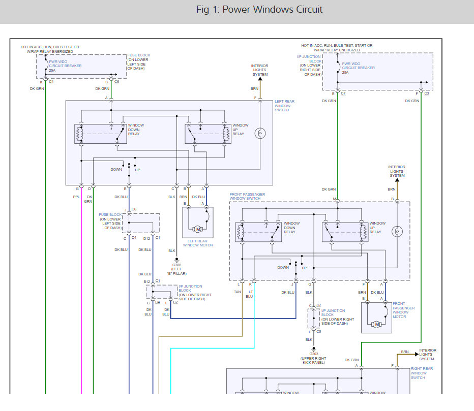
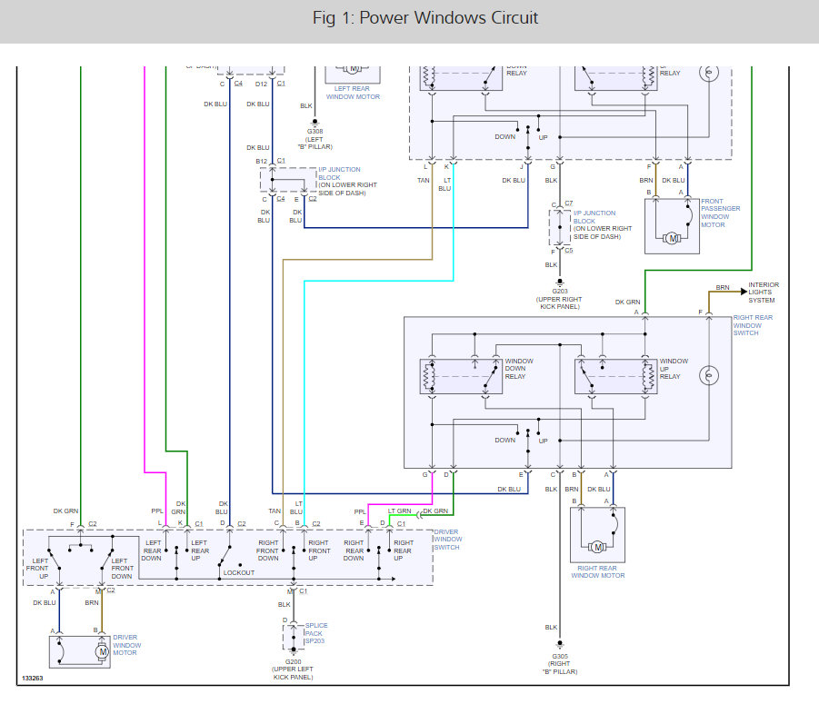
There are relays for each passenger window, up and down, but they are built into the switches. Now I understand why their switches are so expensive. What you will find is the right windows will not work if the driver's switch is unplugged or if the master switch is turned off. Unlike most cars, there ARE separate 12 volt feed wires going into each door that do not originate in the driver's door.

Getting back to the driver's door, double-check the ground circuits. Unplug the motor, the measure between the dark blue wire and ground, and the brown wire and ground. Each of them should be no moe than one or two ohms. This will test one half of each of the two contacts. Be sure to ground your meter to the car body, not the door.

If both circuits test ok, switch to voltage and measure on each motor wire. On the dark blue wire, 12 volts must appear when you press the "Up" botton. 12 volts must appear on the brown wire when the "Down" button is pressed.

I don't see any orange wires anywhere on this diagram. If voltage is not present on the dak blue and brown wires, measure on the dark green wire. That is the feed for the, .... AHA! That's the feed for the two left side switches. There is a 25 amp circuit breaker for the right side switches. There is a DIFFERENT 25 amp circuit breaker for the left side and it feeds both of them. Here's the weird thing. There is a second dark green wire on the driver's switch that comes from the rear switch. Voltage can read through the "Up" relay coil to the left switch. A test light would be dim, but a voltmeter will read full battery voltage. I can't tell you how to tell if you're measuring on the right wire, but if you have 12 volts on both of 'em, they should be good.

If 12 volts is missing on the dark green wires on both left switches, look for the circuit breaker. You can switch it with the right one. If the right side still works, and the left side doesn't, the circuit breaker is tripping for a reason. It will feel warm too.

Caradiodoc
Was this
answer
helpful?
Yes
No
Monday, March 22nd, 2010 AT 6:01 PM
Tiny
BARRETTGR
  • MEMBER
  • 7 POSTS
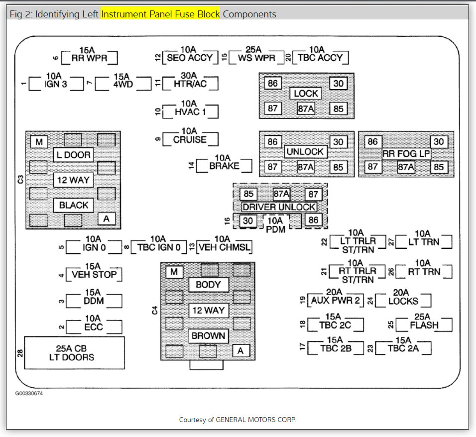
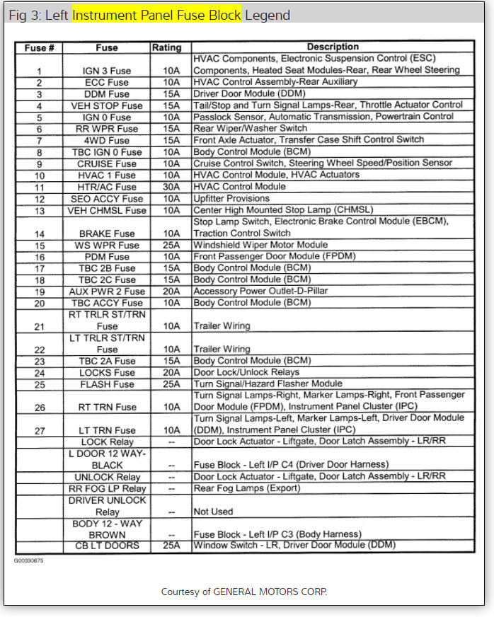
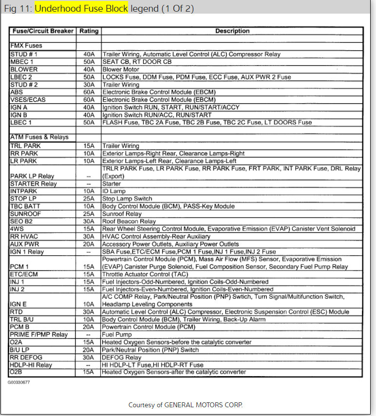
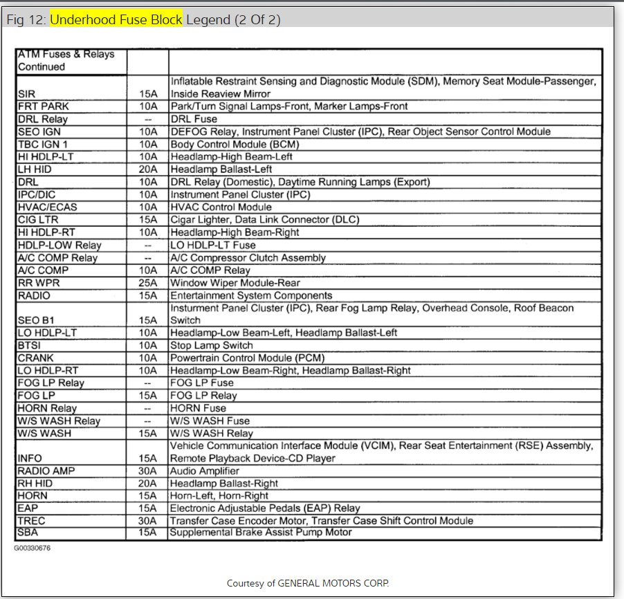
I hear you. Now the problem is I only saw 2 25 amp circuit breakers in the fuse panel and it didn't matter if I had them in or out, switched around - same right side windows work and left don't. So my deduction is I'm not looking at the correct circut breakers. Any idea where they are? Is is possible they are in the BCM?
Was this
answer
helpful?
Yes
No
+1
Tuesday, March 30th, 2010 AT 10:21 AM
Tiny
CARADIODOC
  • MECHANIC
  • 33,750 POSTS
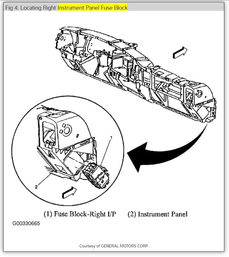
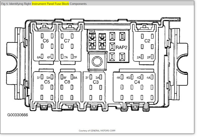
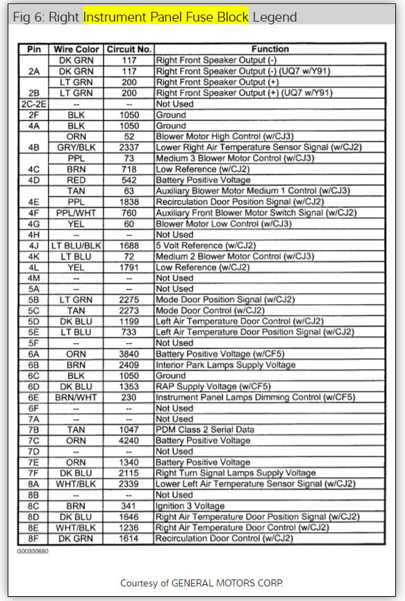
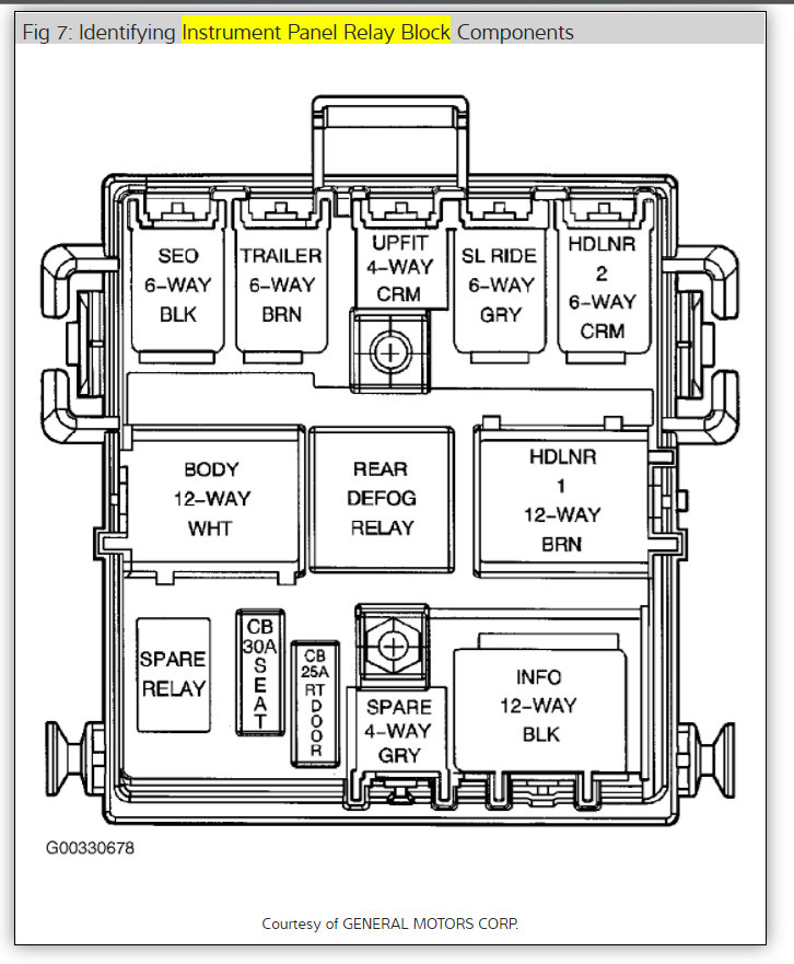
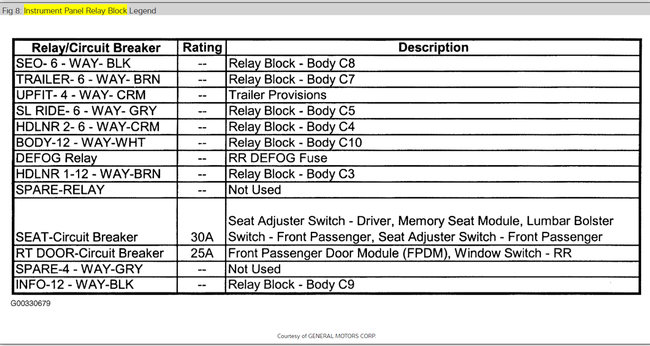
The left circuit breaker is listed as being in the fuse box on the lower left side of the dash. The right one is listed in the junction block on the lower right side of the dash. There's no reference to the Body Computer.

Caradiodoc
Was this
answer
helpful?
Yes
No
Tuesday, March 30th, 2010 AT 11:51 AM
Tiny
BARRETTGR
  • MEMBER
  • 7 POSTS
Yes I found that one on the left. I took the right and swapped it to verify the cb was okay and it did let me operate the left side. I also verfied 12 volts at the power side of the left side cb. Very hot, like there is a short. Had to use pliers to hold it.
Was this
answer
helpful?
Yes
No
Wednesday, March 31st, 2010 AT 11:15 AM
Tiny
CARADIODOC
  • MECHANIC
  • 33,750 POSTS
If either circuit breaker gets hot when it's in the left side, there is something shorted on that line. Start by unplugging the two left switches to eliminate a problem with them. There should be 12 volts on one of the dark green wires. There should be no current flow with the switches unplugged. A fast way to check is to replace the circuit breaker with a small 12 volt light bulb. The bulb should be off. If it is bright, there is a short on the dark green wire to ground. Look for frayed wires between the door hinges or pinched wires under the sill plates, or screws run through the harness under the sill plates.

Caradiodoc
Was this
answer
helpful?
Yes
No
Wednesday, March 31st, 2010 AT 12:53 PM
Tiny
BARRETTGR
  • MEMBER
  • 7 POSTS
Ok we got it. It was the left rear window switch. I kind of fell into it. Before today, I was testing for power at the LR switch, didn't find any so left the switch plugged in and moved to the left front. No power. You know the thread.

This time I took the LR switch out and trouble shooted the LF. Guess what. Everything worked in the LF. Then I took the RR switch since same part number and plugged it in. Now my LR window works too.

I can not see any physical or obvious damage to the LR switch but it does have a "relay looking" type box on it.

So I'll buy a new switch. Thanks for all your patience and advice.
Was this
answer
helpful?
Yes
No
Wednesday, March 31st, 2010 AT 4:05 PM
Tiny
CARADIODOC
  • MECHANIC
  • 33,750 POSTS
DANDY! One in a row! You might consider hunting for a switch in the salvage yards. Much less expensive and I'm guessing the failure rate is pretty low so your chances of getting a bad one are low too. If you autopsy the old switch, look for rust between the contacts in one of the relays in the switch assembly, or one of the contact arms is broken off and staying switched on.

Thank you for the donation. Come back and visit us again.

Caradiodoc
Was this
answer
helpful?
Yes
No
+2
Wednesday, March 31st, 2010 AT 4:35 PM
Tiny
MIKE RICHEY
  • MEMBER
  • 13 POSTS
Hello, so the LR switch was bad causing overcurrent to CB. Causing CB to warm up. If so I have same problem 2001 Tahoe PWR WDO cb 25 A gets hot. LF LR windows non op. No power at master switch. Dark green wire 0 volts good continuity from switch to fuse box.
Was this
answer
helpful?
Yes
No
Sunday, December 13th, 2020 AT 3:48 AM
Tiny
KEN L
  • MASTER CERTIFIED MECHANIC
  • 42,949 POSTS
Usually the switch does not heat up when bad it will be the motor. Can you unplug the window motors and see if the switch gets hot can you see if the relays are hot as well? Here are the wiring diagrams so you can see how the system works. Check out the diagrams (below). Please let us know what happens.
Was this
answer
helpful?
Yes
No
Thursday, December 17th, 2020 AT 4:46 PM

Please login or register to post a reply.

Sponsored links