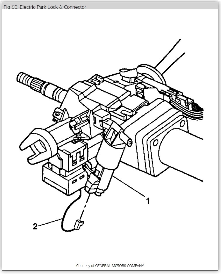
Ignition key lock removal and installation.
Disconnect negative battery cable. Position steering wheel half way between upper and lower tilt stops. Remove steering wheel. Roll back shift lever seal from upper and lower steering column trim covers. Remove tilt wheel lever. Remove lower steering column trim cover. Remove screws retaining upper trim cover. Lift trim cover to gain access to lock cylinder access hole.
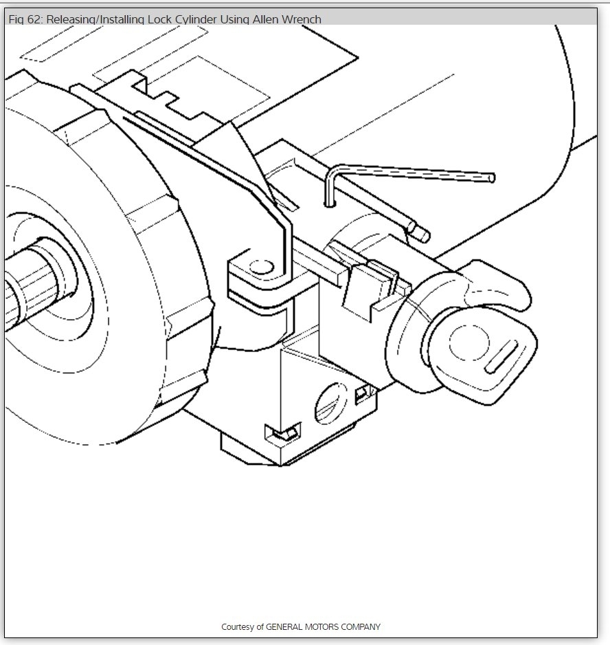
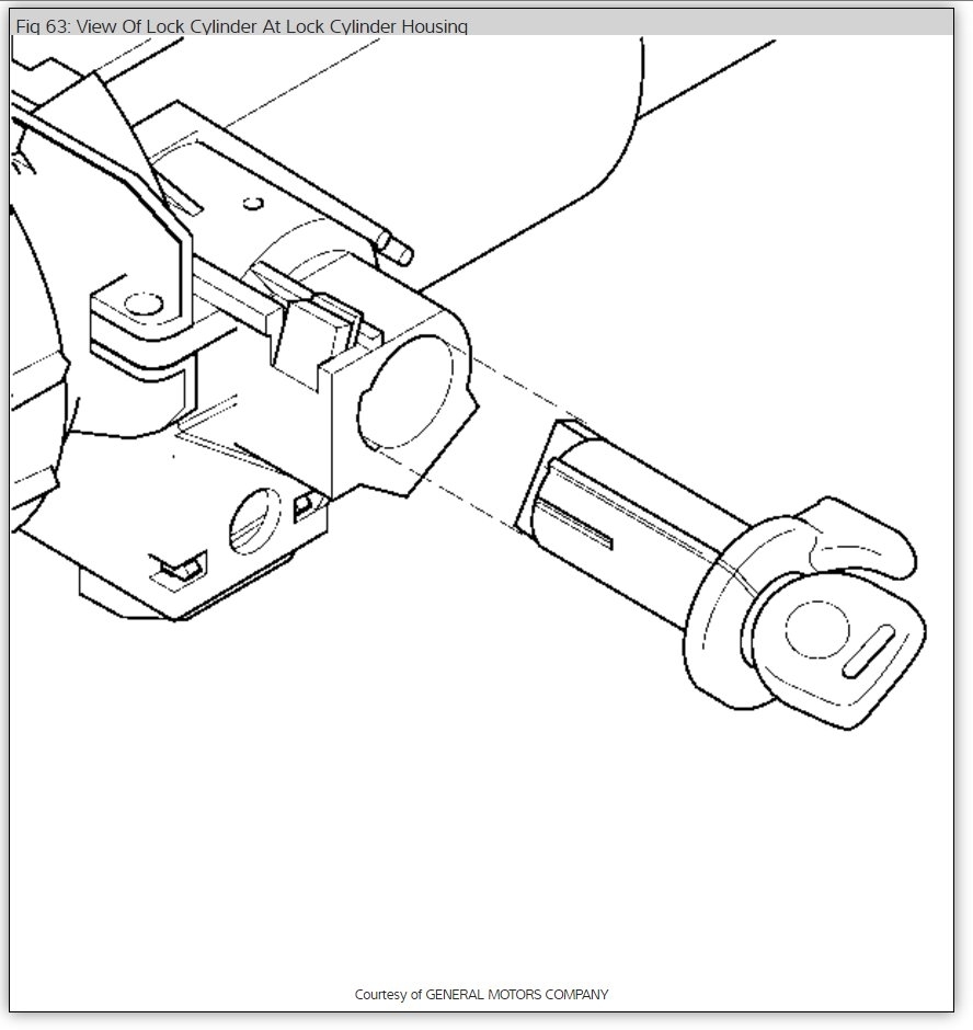
Hold ignition switch in start position. Using a bent tip awl, push on lock cylinder retaining pin. Release ignition switch to run position, and pull lock cylinder set from lock module assembly. See Fig. 5 .
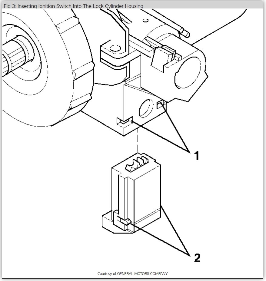
To install, insert key into lock cylinder and turn to run position. Ensure sector in lock module assembly is in run position. Insert lock cylinder into lock module. Align locking and positioning tabs with slots in lock module assembly, and press lock cylinder into position. To complete installation, reverse removal procedure.
Fig. 5: Lock Cylinder Removal
LOCK CYLINDER (NON-FUNCTIONAL)
Disconnect negative battery cable. Remove steering wheel. See STEERING WHEEL . Remove tilt lever. Remove 2 lower shroud screws. Tilt lower shroud down and slide back to disengage locking tabs, and then remove lower shroud. Remove upper shroud retaining screws.
Remove retaining ring. Remove SIR coil assembly. See appropriate AIR BAG RESTRAINT SYSTEMS article. Remove wave washer. Using Lock Plate Compressor (J-23653-SIR), remove and discard retaining ring. Remove shaft lock shield assembly. Remove turn signal cancel cam.
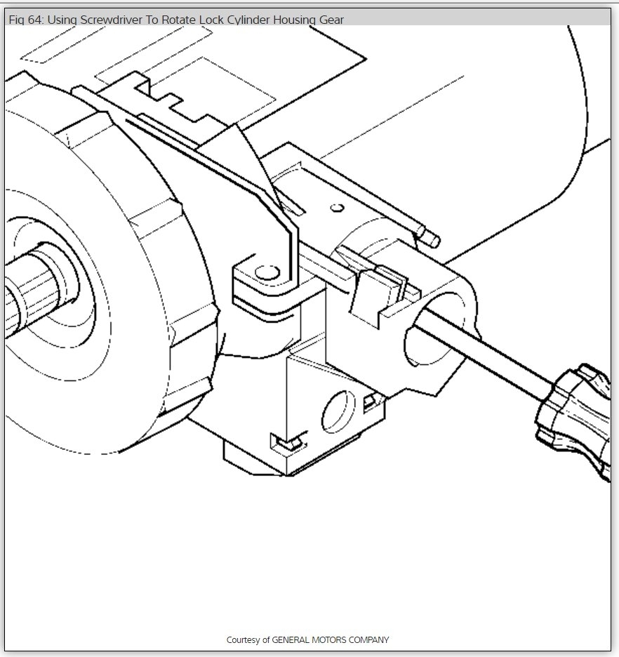
On models with park lock cable, ensure lock cylinder is in OFF-LOCK position and gear shift is in Park. Insert small screwdriver into slot in lock module assembly, push against locking tab on end of cable, and remove park lock cable.
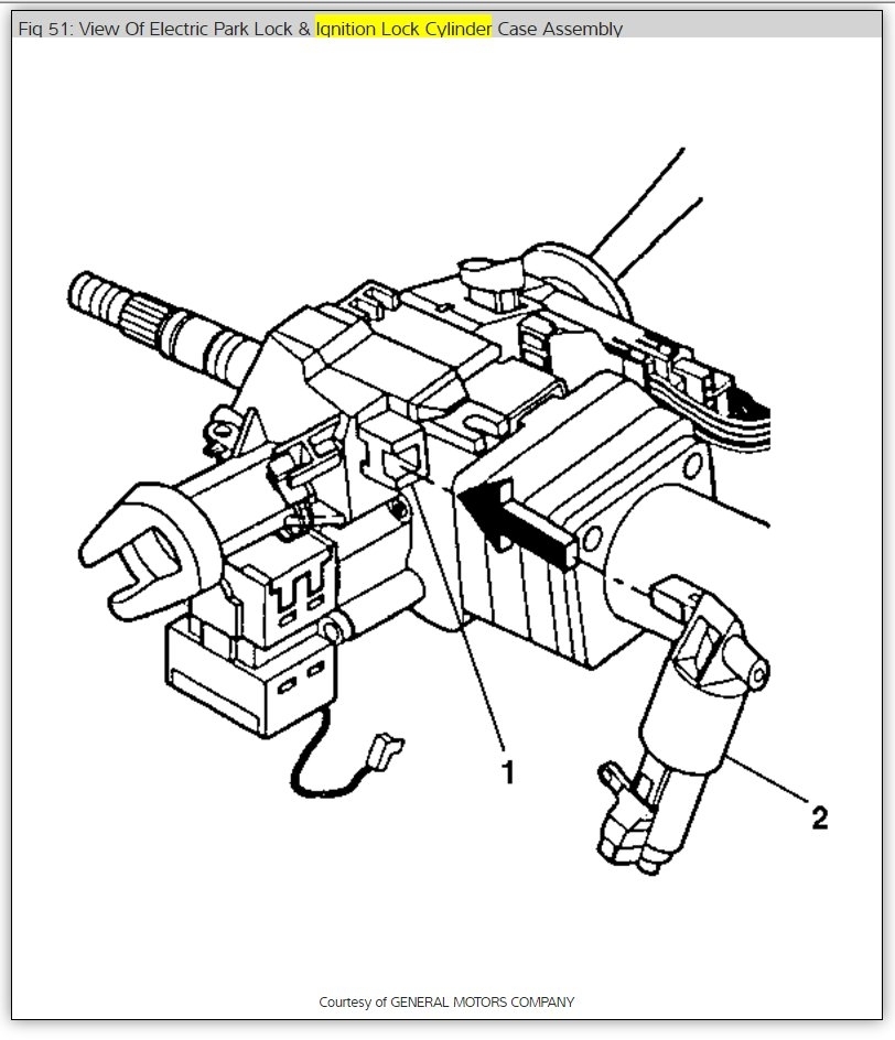
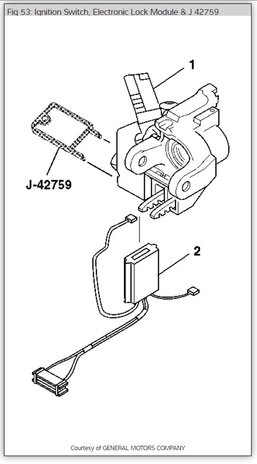
On all models, remove 3 screws, and remove lock module assembly with upper shroud. Remove backing plate from lock module assembly. Mark 2 sector gears at OFF-LOCK position for reassembly reference. See Fig. 6 . Remove both sector gears.
Using an 1/8" burring tool, remove positioning tab on end of lock cylinder. See Fig. 7 . Remove all burrs in and around lock module assembly and lock cylinder. From inside lock module assembly, push on locking tab and pull out lock cylinder. Clean debris from lock module assembly.
Installation
NOTE:Ensure 2 sector gears are properly aligned in OFF-LOCK position, or lock cylinder and ignition switch will be improperly timed.
Install sector gears and backing plate to lock module assembly, ensuring reference marks are aligned. Ensure sector in lock module assembly is in OFF-LOCK position. Insert key in lock cylinder, and turn ignition switch to LOCK position. Align locking and position tabs with slots in lock module assembly and press lock cylinder into position.
Turn lock cylinder to ACC position, and check alignment of arrows on sector gears (arrows should be pointing at each other). Turn lock cylinder back to OFF-LOCK position.
To complete installation, reverse removal procedure. When installing turn signal canceling cam, lubricate lower brass surface with synthetic grease. Use NEW shaft lock retaining ring. Tighten all screws.
Check out the diagrams (below). Please let us know if you need anything else to get the problem fixed.
Cheers
Images (Click to enlarge)
Apr 6, 2021 at 6:46 PM