Hi,
Brakes are a wear item. From use, they go bad. They are not too hard to replace. Take a look through this link. It explains in general how brake pads and rotors are replaced.
https://www.2carpros.com/articles/how-to-replace-front-brake-pads-and-rotors-fwd
Here are directions specific to your vehicle for replacement. The directions also explain how to check things such as the rotors to make sure they are good as well as if the calipers need rebuilt. The attached pics correlate with the directions.
________________________________
2004 Toyota Camry L4-2.4L (2AZ-FE)
Front
Vehicle Brakes and Traction Control Disc Brake System Service and Repair Procedures Front
FRONT
pic 1
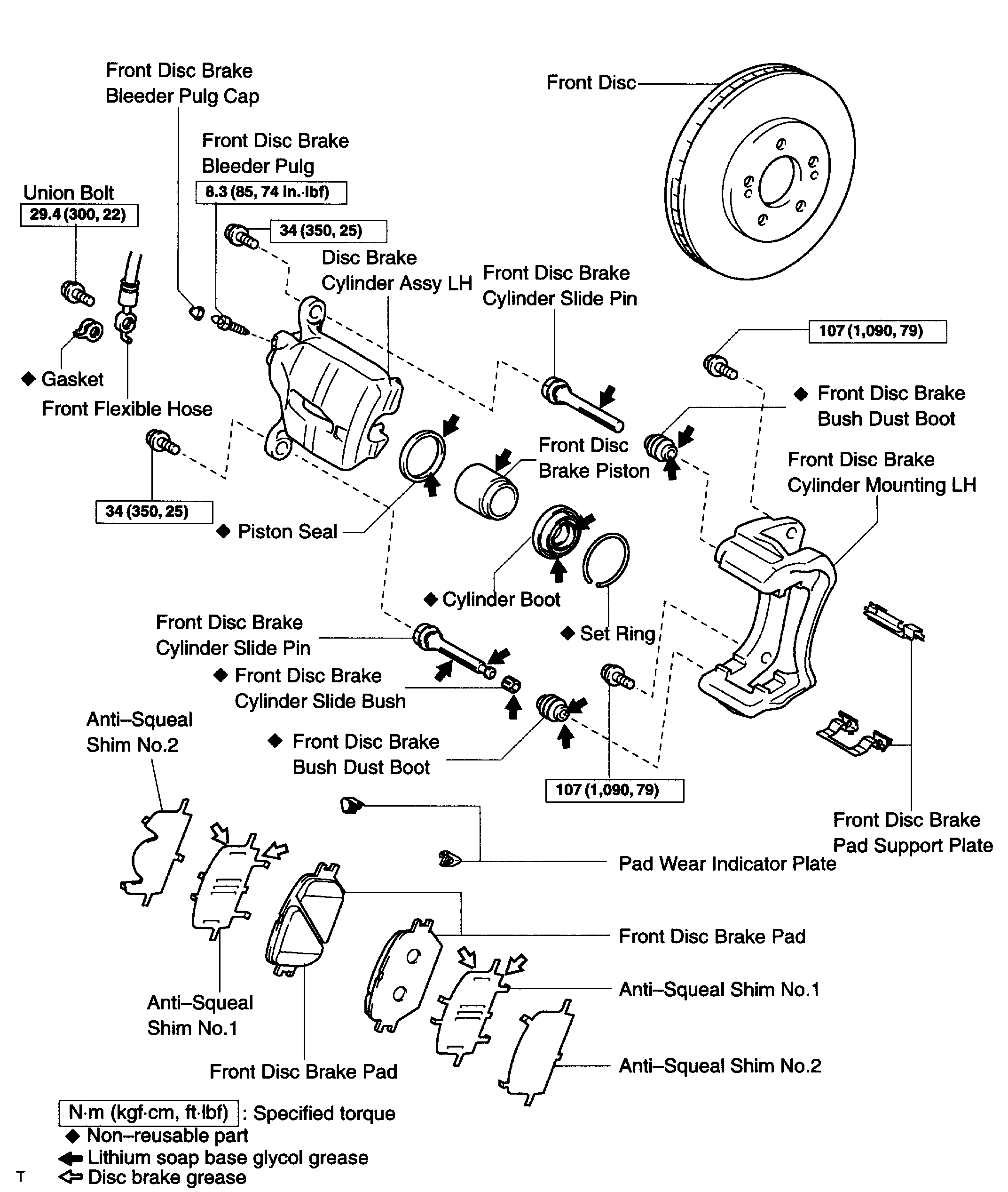
OVERHAUL
HINT:
^ Overhaul the RH side by the same procedures with LH side.
1. REMOVE FRONT WHEEL
2. DRAIN BRAKE FLUID
NOTICE: Wash off the brake fluid immediately if it comes into contact with a painted surface.
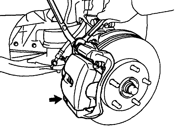
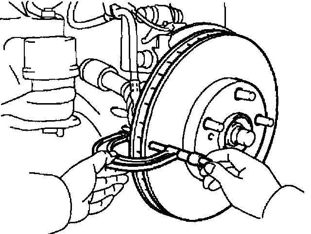
3. DISCONNECT FRONT FLEXIBLE HOSE
a. Remove the union bolt and a gasket from the disc brake cylinder, then disconnect the flexible hose from the disc brake cylinder.
pic 2
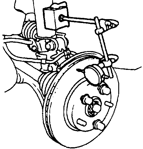
4. REMOVE DISC BRAKE CYLINDER ASSY FR LH
a. Remove the 2 bolts and disc brake cylinder.
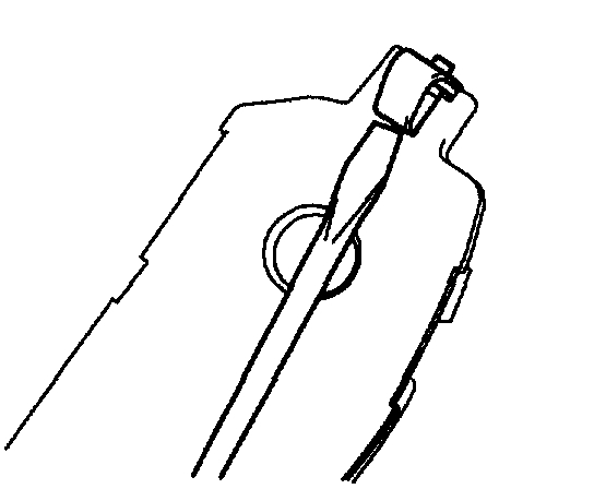
5. REMOVE DISC BRAKE PAD KIT FRONT (PAD ONLY)
a. Remove the 2 brake pads with anti-squeal shim.
pic 3
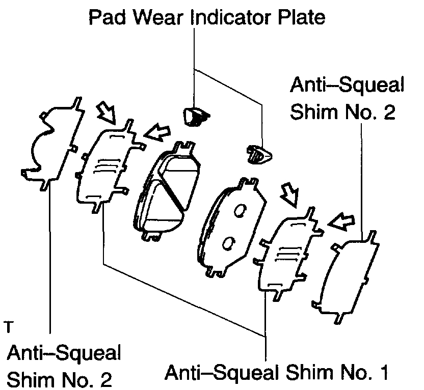
6. REMOVE ANTI SQUEAL SHIM KIT FRONT
a. Remove the 2 anti-squeal shims from each of 2 brake pads.
b. Using a screwdriver, remove the wear indicator from each of 2 brake pads.
7. REMOVE FRONT DISC BRAKE PAD SUPPORT PLATE
a. Remove the upper side front disc brake pad support plate.
8. REMOVE FRONT DISC BRAKE PAD SUPPORT PLATE
a. Remove the bottom side front disc brake pad support plate.
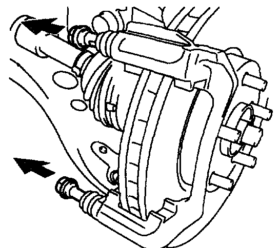
pic 4
9. REMOVE FRONT DISC BRAKE CYLINDER SLIDE PIN
a. Remove the 2 cylinder slide pins from the disc brake cylinder mounting.
pic 5
10. REMOVE FRONT DISC BRAKE CYLINDER SLIDE BUSH
a. Remove the cylinder slide bush from the cylinder slide pin.
11. REMOVE FRONT DISC BRAKE BUSH DUST BOOT
a. Remove the 2 bush dust boots from the disc brake cylinder mounting.
12. REMOVE FRONT DISC BRAKE CYLINDER MOUNTING LH
a. Remove the 2 bolts and disc brake cylinder mounting LH.
pic 6
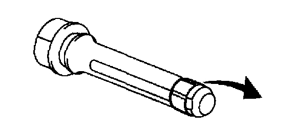
13. REMOVE CYLINDER BOOT
a. Using a screwdriver, remove the set ring and cylinder boot.
pic 7
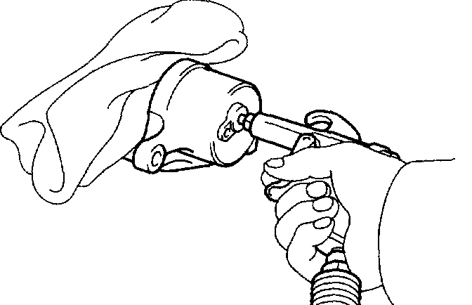
14. REMOVE FRONT DISC BRAKE PISTON
a. Place a piece of cloth or similar, between the piston and the disc brake cylinder.
b. Use compressed air to remove the piston from the disc brake cylinder.
CAUTION: Do not place your fingers in front of the piston when using compressed air.
NOTICE: Do not spatter the brake fluid.
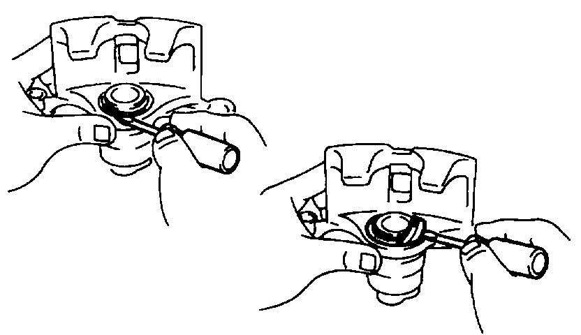
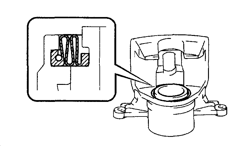
15. REMOVE PISTON SEAL
a. Using a screwdriver, remove the piston seal from the disc brake cylinder.
NOTICE: Do not damage the inner cylinder and the cylinder groove.
16. REMOVE FRONT DISC BRAKE BLEEDER PLUG CAP
17. REMOVE FRONT DISC BRAKE BLEEDER PLUG
18. INSPECT BRAKE CYLINDER AND PISTON
Check the cylinder bore and piston for rust and scoring
pic 8
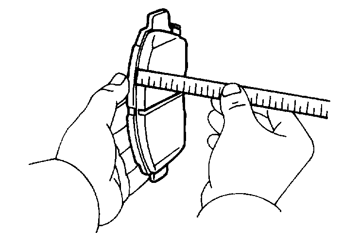
19. INSPECT PAD LINING THICKNESS
a. Using a ruler, measure the pad lining thickness.
Standard thickness: 12.0 mm (0.472 inch)
Minimum thickness: 1.0 mm (0.039 inch)
20. INSPECT FRONT DISC BRAKE PAD SUPPORT PLATE
a. Make sure that they have sufficient rebound, no deformation cracks or wear, and have had all rust and dirt cleaned off.
21. INSPECT FRONT DISC BRAKE PAD SUPPORT PLATE
a. Make sure that they have sufficient rebound, no deformation cracks or wear, and have had all rust and dirt cleaned off.
pic 9
22. INSPECT DISC THICKNESS
a. Using a micrometer, measure the disc thickness.
Standard thickness: 28.0 mm (1.102 inch)
Minimum thickness: 26.0 mm (1.024 inch)
pic 10
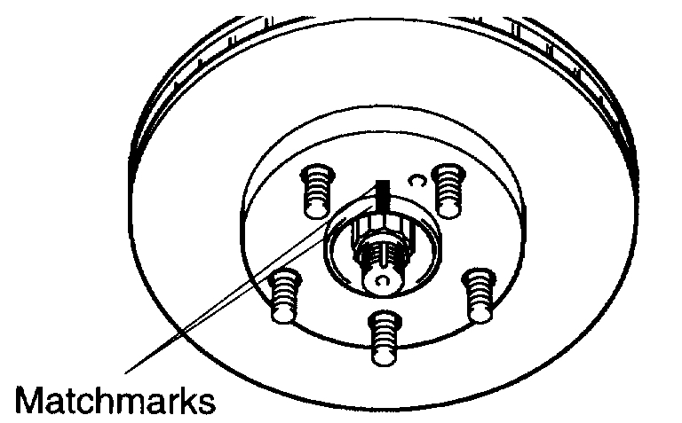
23. REMOVE FRONT DISC
a. Put matchmarks on the disc and the axle hub.
b. Remove the disc.
24. INSTALL FRONT DISC
a. Aligning the matchmarks, install the front disc.
HINT: When replacing the disc with a new one, select the installation position where the disc has the minimum value.
pic 11
25. INSPECT DISC RUNOUT
a. Temporarily fasten the disc with hub nuts.
Torque: 103 Nm (1,050 kgf-cm, 76 ft. lbs.)
b. Using a dial indicator, measure the disc runout 10 mm (0.39 inch) away from the outer edge of the disc.
Maximum disc runout: 0.05 mm (0.0020 inch)
c. If the disc's runout is maximum value or greater, check the bearing play in the axial direction and check the axle hub runout. If the bearing play and axle hub runout are not abnormal, adjust the disc runout or grind it on a "On-car" brake lathe.
26. TEMPORARY TIGHTEN FRONT DISC BRAKE BLEEDER PLUG
a. Temporarily tighten the bleeder plug to the disc brake cylinder.
27. INSTALL FRONT DISC BRAKE BLEEDER PLUG CAP
28. INSTALL PISTON SEAL
a. Apply the lithium soap base glycol grease on a new piston seal.
b. Install the piston seal to the disc brake cylinder.
29. INSTALL FRONT DISC BRAKE PISTON
a. Apply the lithium soap base glycol grease on the piston.
b. Install the piston to the disc brake cylinder.
NOTICE: Do not screw the piston forcedly in the disc brake cylinder.
pic 12
30. INSTALL CYLINDER BOOT
a. Apply the lithium soap base glycol grease on a new cylinder boot. Install the cylinder boot to the disc brake cylinder.
HINT: Install the boot securely to the grooves of the cylinder and piston.
b. Using a screwdriver, install the set ring.
NOTICE: DO not damage the cylinder boot
31. INSTALL FRONT DISC BRAKE CYLINDER MOUNTING LH
a. Install the disc brake cylinder mounting LH with the 2 bolts.
Torque: 107 Nm (1,090 kgf-cm, 79 ft. lbs.)
32. INSTALL FRONT DISC BRAKE BUSH DUST BOOT
a. Apply the lithium soap base glycol grease to seal surface of 2 new bush dust boots.
b. Install the 2 bush dust boots to the disc brake cylinder mounting.
33. INSTALL FRONT DISC BRAKE CYLINDER SLIDE BUSH
a. Apply the lithium soap base glycol grease to a new cylinder slide bush.
b. Install the cylinder slide bush to the cylinder slide pin.
34. INSTALL FRONT DISC BRAKE CYLINDER SLIDE PIN
a. Apply the lithium soap base glycol grease to the sliding part and the seal surface of the 2 cylinder slide pins.
b. Install the 2 cylinder slide pins to the disc brake cylinder mounting.
HINT: Place with the bush side facing down.
35. INSTALL FRONT DISC BRAKE PAD SUPPORT PLATE
a. Install the upper side front disc brake pad support plate.
36. INSTALL FRONT DISC BRAKE PAD SUPPORT PLATE
a. Install the bottom side front disc brake pad support plate.
pic 13
37. INSTALL ANTI SQUEAL SHIM KIT FRONT
NOTICE:
^ When replacing worn pads, the anti-squeal shims must be replaced together with the pads.
^ Install the shims and pad wear indicator plates correctly of which positions and directions.
a. Apply disc brake grease to inside of each anti-squeal shim No. 1.
b. Install the anti-squeal shim No. 1 and No. 2 on each pad.
c. Install the pad wear indicator plate to the 2 pads.
38. INSTALL DISC BRAKE PAD KIT FRONT (PAD ONLY)
a. Install the 2 pads with the pad wear indicator plate facing upward.
NOTICE: There should be no oil or grease adhering to the friction surfaces of the pads and the disc.
39. INSTALL DISC BRAKE CYLINDER ASSY FR LH
a. Install the disc brake cylinder with the 2 bolts.
Torque: 34 Nm (350 kgf-cm, 25 ft. lbs.)
40. CONNECT FRONT FLEXIBLE HOSE
a. Install a new gasket and flexible hose with the union bolt.
Torque: 29.4 Nm (300 kgf-cm, 22 ft. lbs.)
HINT:
^ Gasket has 2 types: 2-piece type and 1-piece type.
^ Install the flexible hose lock securely in the lock hole in the disc brake cylinder.
41. FILL RESERVOIR WITH BRAKE FLUID
42. BLEED MASTER CYLINDER
SST 09023-00100
43. BLEED BRAKE LINE
44. CHECK FLUID LEVEL IN RESERVOIR
45. CHECK BRAKE FLUID LEAKAGE
46. INSTALL FRONT WHEEL
Torque: 103 Nm (1,050 kgf-cm, 76 ft. lbs.)
___________________________________________
I hope this helps. Let me know if you have questions.
Take care and God Bless,
Joe
Images (Click to enlarge)
Mar 11, 2021 at 12:38 PM