1999 Dodge Durango PCM/BCM

Tiny
DIVERJIM
  • MEMBER
  • 1999 DODGE DURANGO
  • 162,000 MILES
We just had a new PCM put into this car in March 2013. We then had a transmission issue (started dropping out of gear and speedometer not working properly). Turns out the PCM they put in had a cracked circuit board. Aamco said that the bad PCM caused damage to the overdrive in the transmission. Had to rebuild the transmission. But when we got it back, we still had some of those same issues (dropping out of gear and speedometer, etc.). Dealer replaced the PCM again. As soon as we got it back, the "check engine" light would come on, the check gauges light and the airbag light would randomly turn on and off, and several of the gauges (voltage, fuel & oil pressure) would peg at the extremes. Even had the car turn off all by itself, and the idling was rough. The dealership said that by a "massive coincidence", the BCM has now failed once they replaced the PCM! We say they damaged the BCM when they put in the new PCM. Dealer says that is not possible since they do not have anything to do with each other.
Tuesday, June 18th, 2013 AT 3:57 AM

8 Replies

Tiny
CARADIODOC
  • MECHANIC
  • 33,743 POSTS
Lots of misinformation in your story. First of all, you are wrong about the mechanic damaging the Body Computer. While it is possible to intentionally do that, it would take a lot of effort to purposely do something like remove wires from the connectors and reattach them in the wrong order.

Second, it's highly doubtful anyone would get an Engine Computer with a "cracked board". They are sealed in a protective jelly inside the housing and are real hard to get out. I've taken some out to purposely damage one tiny circuit to create problems for my students to diagnose, and it's not an easy job. The boards are really tough and almost impossible to break. If one would be cracked in a previous crash it would have been rejected by the rebuilder and it certainly would not have passed their performance checks. If this was a used computer from a salvage yard and it came from a vehicle that was in a crash there would certainly be evidence of that on the housing.

Third, computer and other electrical problems will not cause physical damage to the transmission. When an electrical problem occurs the system will put the transmission into second gear and it will stay there until you turn the ignition switch off and restart the engine. A physical problem will not result in the speedometer quitting. That points to an electrical problem.

You have a bunch of electrical problems in all different circuits so I would start by looking for things they all have in common. Since the Air Bag light turned on, check that computer for diagnostic fault codes. Those may give a hint as to the cause. The Body Computer talks back and forth with the instrument cluster, which is also a computer module, and either one could be responsible for the warning lights in multiple circuits turning on.

It's interesting too that the transmission problem you described was supposedly fixed once by rebuilding it, then fixed for the same thing by replacing the Engine Computer. Instead, start with some more common things like a defective alternator. Have it load-tested to see what it will deliver for maximum current and "ripple" voltage. If it will only deliver exactly one third of its design rating for current and ripple is high, it has a bad diode. 35 amps from the common 100 amp alternator is not enough to meet the demands of the electrical system under all conditions. Computers hate low system voltage and excessive ripple, (variations in voltage), and they'll do weird things, like turn on warning lights, and turn things on and off.

Also look at the smaller battery wires where they attach to the under-hood fuse box and body. Those often become loose on any brand of vehicle and cause intermittent no-start conditions to flashing dash lights while driving. Those are a couple of examples of things that are in common with all the systems you're having trouble with.
Was this
answer
helpful?
Yes
No
-1
Tuesday, June 18th, 2013 AT 10:32 AM
Tiny
DIVERJIM
  • MEMBER
  • 3 POSTS
Hmmm. Not sure what to think.

First of all, the DEALER is the one that said the 2nd PCM had a cracked circuit board, so I can only take their word for it and assume that info is correct.

Also, it's the DEALER that said their diagnostics indicated a bad BCM after installing the 3rd PCM. But not previously? That seems extremely unlikely. They did a diagnostic check after they installed the 2nd PCM, so why wouldn't the "bad" BCM have shown up then? And the dealer says they use NEW OEM parts, not re-built units (although I wonder).

As far as the transmission repair, the mechanic who did the transmission work (a 30-year veteran) said that the bad/cracked PCM (he didn't know it was cracked, by the way) could have caused the damage to the tranny overdrive since it sends control commands to it. And they were able to determine that by just tapping the side of the PCM, they could get the vehicle to do strange things! That's how they figured out the PCM was bad and not the re-built transmission. It was at that point that I had to take it back to the dealer.

I see that there could be other issues going on. Could bad voltage cause the diagnostics to show false readings, like indicating a bad BCM, even though it may not really be malfunctioning? The strange behavior of the indicators was NOT something that was occurring before they did the last replacement of the PCM, but showed up immediately after I got it back from the dealer when they installed the 3rd PCM. Could a faulty electrical system have caused this whole mess? And if so, wouldn't the dealer's diagnostics show that?

I'm so confused. Seems like a lot of conflicting information! : (
>-sigh-<
Was this
answer
helpful?
Yes
No
-1
Tuesday, June 18th, 2013 AT 1:12 PM
Tiny
CARADIODOC
  • MECHANIC
  • 33,743 POSTS
You've added a few details that made me rethink my response. If tapping on a computer makes it change its behavior, that is indeed a potential sign of a bad solder connection inside but first I'd rule out loose or corroded connector pins. Those terminals are pretty tough and they're well-sealed so the few times I have actually found a problem it was after someone was working in the area or had that connector apart.

Most of the time new computers are very expensive so it's customary to get rebuilt units, even through the dealer. I worked for a very nice Chrysler dealership all through the '90s and the only times we got brand new computers was when the vehicle was under warranty and Chrysler was paying the bill. When customers were paying the bill we always installed rebuilt, (remanufactured) computers to save money, and I don't recall ever having a problem.

There's a lot of computers on your vehicle and they all talk back and forth to each other over two wires called the "data buss". You can't damage one computer by having another one send out harmful information on that data buss. That's why I'm looking for a different cause for the multiple problems, and the charging system is the one that is responsible most often. GM owners know more about that because they have a huge problem with their generators developing voltage spikes that cause damage and interfere with computers and their sensor signals. ("Generator" is the new industry standardized term. The common term is "alternator" but that was actually used first by Chrysler in 1960 and they copyrighted that term).

There really isn't anything simple a mechanic can do to accidentally damage a computer. All mechanics live in constant fear of parts failing while we're working on the vehicle, then having to explain that to the owners, but it happens quite often. I run into that with some of the radios I'm asked to fix and there is one specific problem that DOES occur when the mechanic has to disconnect the battery. When he reconnects it later is when the radio is dead, so of course the owner "knows" the mechanic caused the problem, but I have the service bulletin that explains how the problem actually developed months or years earlier. It just won't show up until power to it is disconnected for a while.

That's one example of what I mean by living in fear of something breaking while we have your car. Most such problems are more varied and random. I would be suspicious too, but when that happens to my vehicles it's me who is working on it so I don't have to worry about who gets the blame.

I don't have a good answer about how they did the diagnostic tests and what would show up. We rely pretty heavily on diagnostic fault codes that can be set and stored in every computer. A lot of codes point specifically to an internal failure inside a computer but most codes relate to external sensors and actuators or the wiring to them. In the absence of any codes, about all you can do is condemn a computer if it isn't performing the proper functions. My concern is there is an underlying cause in a different circuit that got overlooked and is causing the incorrect behavior. We never like throwing random parts at a problem, but in the case of a computer, if the problem goes away when you substitute a new one, that pretty much proves there is no other defect.
Was this
answer
helpful?
Yes
No
-1
Wednesday, June 19th, 2013 AT 1:20 AM
Tiny
DIVERJIM
  • MEMBER
  • 3 POSTS
Thanks, doc.I'm having a 3rd party auto repair facility check into the possibility of some kind of voltage/electrical problem as the primary cause. Hopefully they can find the real culprit.

Thank you so much for your helpful insight!

Kind regards, - Jim
Was this
answer
helpful?
Yes
No
Thursday, June 20th, 2013 AT 9:08 AM
Tiny
JOE MAROTTA
  • MEMBER
  • 2 POSTS
It's probably 98% chance the voltage regulator in the PCM is hanging up from time to time throwing 16 or higher volts into the system causing all of these haunting problems.
I had it happen to my 99 Durango and have seen is on numerous Dodge and Ford, except Ford doesn't have the voltage regulator in their ECM, it's still in the Alternator, Not sure of the newest ones of coarse. The best thing I ever did for my Durango was to fuse the Regulator in and out of the PCM with those nice little fuse holders they sell for almost nothing.
A must for me is a little volt meter that stays plugged into the cigarette lighter.
That saved my life when the PCM's regulator stuck, because when you get that high of voltage sometimes all the gauges blink out for safety reasons not letting you see the factory dash cluster charge gauge.
Was this
answer
helpful?
Yes
No
Thursday, April 25th, 2019 AT 4:00 PM
Tiny
CARADIODOC
  • MECHANIC
  • 33,743 POSTS
It sounds like you're describing the old mechanical voltage regulator that had contact points that could arc together and stick. In fact, Chrysler's regulators inside the Engine Computer have been uncommonly reliable, and unlike those in all other car brands, they can turn the alternator off when maximum power is needed at wide-open-throttle, and they can tweak charging voltage for all the variables the computer knows.

There's only one control wire between the computer and one of the smaller field terminals on the alternator. There's no value in putting a fuse in that circuit. If that wire was to rub through and ground out to the engine or body, the alternator will charge wide-open with system voltage going too high, but that field current will still be limited by the resistance of the field coil, which is four ohms. Current can never go higher than four amps, and it can never go higher than three amps when the system is working properly. Under most driving conditions, field current rarely goes higher than one or two amps.

Thanks for adding your experience.
Was this
answer
helpful?
Yes
No
Thursday, April 25th, 2019 AT 4:26 PM
Tiny
JOE MAROTTA
  • MEMBER
  • 2 POSTS
I dont have a schematic in front of me however there is one wire from the alt in and another different one out of PCM.>>>GRAY CONNECTOR >> 25 K125 18WT/DB GENERATOR SOURCE (+) + A >>> WHITE CONNECTOR>>>10 K20 18DG GENERATOR FIELD DRIVER (+)
A 5 amp fuse should blow if the circuit gets too hot, I've seen the coating on those wires melt from this problem. Would blow if It has become so common for these PCM regulators to go out and overcharge the system, they have an external kit to use as the older CHY ones were eliminating the problem. I'm not just basing this on my own vehicle, but so many others.
I'm 62 now, and this as all I've ever done for a living. No shop anymore but it's still in my heart to be aggravated by these things. I've seen some of these huge alternators go past 20 volts and take out almost entire electrical systems.

Well I'll let this go and hope our friend figures out whats going on with his situation.
I have a weak ground to the trans relay, "pink wire from PCM" on the 99 rango I'm messing with now. With the engine, ign off, it still shows a slight ground connection. I barely looked at it, had to take a nap you know but might get after it again in a few. If it's doing it right from the PCM we know what that means. I've never seen one act like this before.
Nice hearing from ya.
Joe
Was this
answer
helpful?
Yes
No
Thursday, April 25th, 2019 AT 5:41 PM
Tiny
CARADIODOC
  • MECHANIC
  • 33,743 POSTS
I was 62 last month, but not now.

The terminology is what makes this confusing. On the diagram, it looks like the current to run the field winding comes out of the PCM, but in fact, that is backward. Well, I gotta qualify that. On the Dakota / Durango, they run the circuit through the computer instead of to the computer.

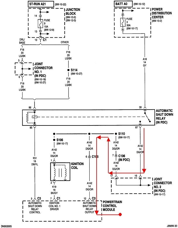
It's the automatic shutdown, (ASD) relay that supplies 12 volts to the field terminal, along with the ignition coil pack, injectors, oxygen sensor heaters, and a few other things. The dark green / orange wire is the "ASD Output" circuit leaving the relay, so that is what they call that wire going into the PCM. That's terminal 12 in connector C3. The "output" circuit is the "input" to the PCM.

When the PCM turns the ASD relay on, this terminal is where the 12 volts appears, to provide proof it got turned on. It always was the 12 volt supply to feed other things that were turned on and off by the computer, but now they needed to complicate the circuit unnecessarily. The white / dark blue wire you have used to be just another dark green / orange, and was spliced right to the other ones that go to the ignition coil and injectors. It still does that, but by way of two terminals that are connected together. In fact, terminals 12 and 25 in connector C3 are right next to each other, and they are connected internally.

My community college was one of three remote training sites for Chrysler in my state. In return for using our facilities, they often donated vehicles to us after they had been poked and prodded by their students. One of them was a Dakota with this same circuit. It was due to a mistake made by a pair of my students that burned that copper trace. Upon taking the PCM apart and finding that, I figured out those two wires could be spliced together outside the computer without changing anything related to how the system works. I can't think of any logical reason to do that except to make the computer easy to destroy through improper diagnostic techniques.

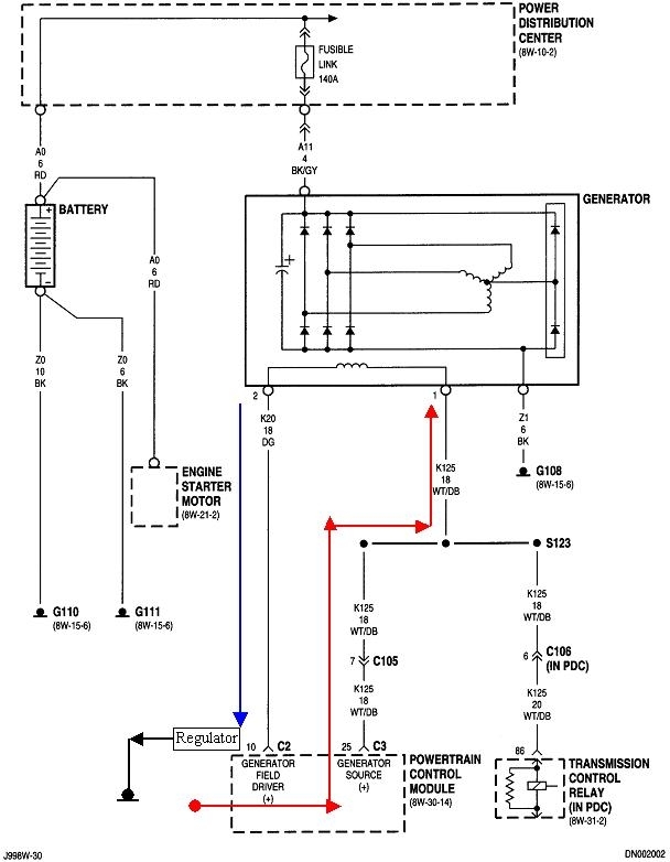
Up to my last red arrow, terminal "1" on the alternator, there will be full system voltage everywhere on that line, with no involvement of the computer other than passing between those two terminals. Terminal "2" on the alternator is the control side that goes to the voltage regulator circuit in the PCM, terminal 10, connector C2, and then to ground to complete the circuit. That has usually been that dark green wire on most models. When the regulator draws this voltage down, the current flow through the field winding creates the electromagnetic field needed to generate the output current and voltage. The lower it draws the voltage down, the greater the difference will be between the two terminals, and the stronger the magnetic field will be. The typical range of voltage you'll find on that wire is between 4 and 11 volts.

One of the clues to determining the cause of over-charging is if that dark green wire is rubbed through and grounded, you'll find 0 volts on terminals "2". If the voltage regulator is shorted, you'll find a minimum of around 2.0 volts. Due to the interconnected internal circuitry, a shorted regulator can't draw the voltage all the way down to 0.0 volts.

If the fuse you added is in the white / dark blue wire, that wire is all it's going to protect. If you accidentally ground terminal "1" at the alternator, the fuse will blow, then only the charging system will be dead. More commonly it will be the dark green orange wire that falls down onto hot exhaust system parts, melts through, and shorts to ground. That would blow the 30-amp fuse "3".

If the voltage regulator were to short, that would be the same as grounding terminal "2", which is what we do to perform the full-field output current test. Field current can't go much higher than 3 amps, so a fuse anywhere in that circuit will never blow.

Most people aren't aware that Chrysler developed the first "AC generator" for 1960 models and copyrighted the term, "alternator". GM was the first to copy the idea, but not until the '64 models. Chrysler also had the first electronic voltage regulator in 1970. That is the one you're referring to as a modification. That is relatively easy to do, and it will work, but that will turn on the Check Engine light, then you'll never know if or when a different problem shows up since the light is already on. Anything the computer detects and sets a fault code for that could adversely affect emissions are the codes that turn on the Check Engine light. The thinking is with low system voltage, the injectors won't fire properly and spark will be weak. Those can increase emissions.

The regulator switches the ground for the dark green wire on and off about 400 times per second, and it varies that "duty cycle" to vary the average field current. When you cut that wire to run to an external regulator, the computer will see the lack of field current through the PCM, and set the fault code, "field current not switching properly". I suggested to the last person contemplating this modification to add a power resistor between the dark green / orange wire and the cut wire at terminal 10, C2. That would give it some current to switch on and off and let it think it's doing its job. That should prevent it from setting a code and turning the Check Engine light on. That would need to be about a four to six ohm resistor, at least a 25 watt. The last person never posted a follow-up to say if that worked.
Was this
answer
helpful?
Yes
No
Friday, April 26th, 2019 AT 11:46 PM

Please login or register to post a reply.

Sponsored links