Hi,
Okay. Now we need to continue testing. There is an ignition coil hall effect sensor that needs checked next. Here are the directions. The attached pic correlates with the directions.
______________________________
1995 Volkswagen Jetta III (1H2) L4-2.0L (ABA)
Component Tests and General Diagnostics
Vehicle Powertrain Management Sensors and Switches - Powertrain Management Sensors and Switches - Ignition System Hall Effect Sensor Testing and Inspection Component Tests and General Diagnostics
COMPONENT TESTS AND GENERAL DIAGNOSTICS
NOTE: The Hall effect sender should only be tested if the engine does not start and there is no spark at the spark plugs. To further assist you during testing, use the wiring diagrams.
CAUTION: Always turn ignition OFF when connecting or disconnecting Hall sender or ignition power stage unit terminals. Be sure to check the integrity of the wires, connectors, battery terminals and fuses before replacing an expensive component.
- Be sure ignition coil is in good working order. If needed, test coil first,
- Be sure ignition power stage unit is in good working order. If needed, test power stage unit after coil test.
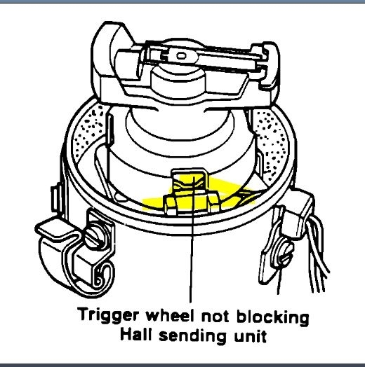
- Remove distributor cap and visually inspect the Hall sender. If shutter wheel is touching the sender, there is corrosion or other damage, replace and retest with new component.
- Disconnect the coil wire from the center of distributor cap and connect it to ground so engine can't start.
Digifant I Coil Power Stage Connector
Pic 1
- Peel back the protective boot connector on the Hall sender harness connector.
- Connect an LED test light between the center connector terminal and either of the outer terminals.
- Turn the engine over using the starter. The LED should flicker.
- If not, replace and retest with new Hall effect sender.
- Disconnect all test equipment, reconnect the coil wire and cover the Hall sender connector with its boot.
__________________________________
Here are the directions for testing the coil. Pic 2 correlates with these directions.
1995 Volkswagen Jetta III (1H2) L4-2.0L (ABA)
Component Tests and General Diagnostics
Vehicle Powertrain Management Ignition System Ignition Coil Testing and Inspection Component Tests and General Diagnostics
COMPONENT TESTS AND GENERAL DIAGNOSTICS
CHECKING IGNITION COIL
- Disconnect harness connector and ignition wire from Ignition Coil (N152).
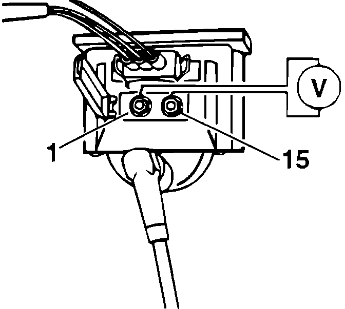
Pic 2
- Check primary resistance between terminals -1- and -15- using Fluke 83 multimeter.
Specified value: 0.5 - 0.7 Ohms.
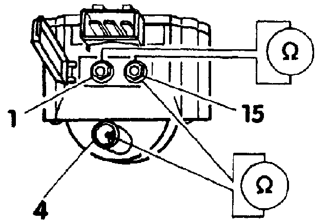
- Check secondary resistance between terminals -4- and -15-.
Specified value: 3000 to 4000 Ohms.
- If NOT OK:
- Remove Ignition Coil and disconnect Ignition Coil Power Output Stage (N157).
- Repeat test.
_________________________________________
Here are the directions for testing the power output stage.
1995 Volkswagen Jetta III (1H2) L4-2.0L (ABA)
Component Tests and General Diagnostics
Vehicle Powertrain Management Relays and Modules - Powertrain Management Relays and Modules - Ignition System Ignition Control Module Testing and Inspection Component Tests and General Diagnostics
COMPONENT TESTS AND GENERAL DIAGNOSTICS
PROCEDURE
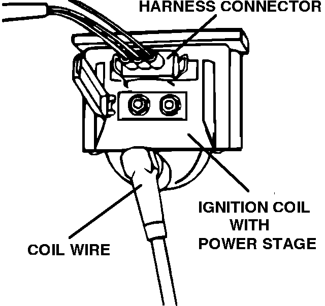
Ignition Coil With Power Stage
Pic 3
- Disconnect the high tension coil wire from the ignition coil output terminal (terminal 4).
- With the ignition "OFF" remove the power stage harness connector.
Digifant I Coil Power Stage
pic 4
- Connect a suitable volt/ohm meter between terminals 1 and 3 of the power stage harness connector.
- Turn ignition switch "ON".
The correct reading should be battery voltage (approx. 12 VDC).
CAUTION:
- Always turn the ignition switch "OFF" before changing meter ranges, and before disconnecting or connecting the meter probes. Doing so with the ignition switch turned "ON" risks permanent control unit damage.
- If not, wiring harness may be defective check and repair as necessary.
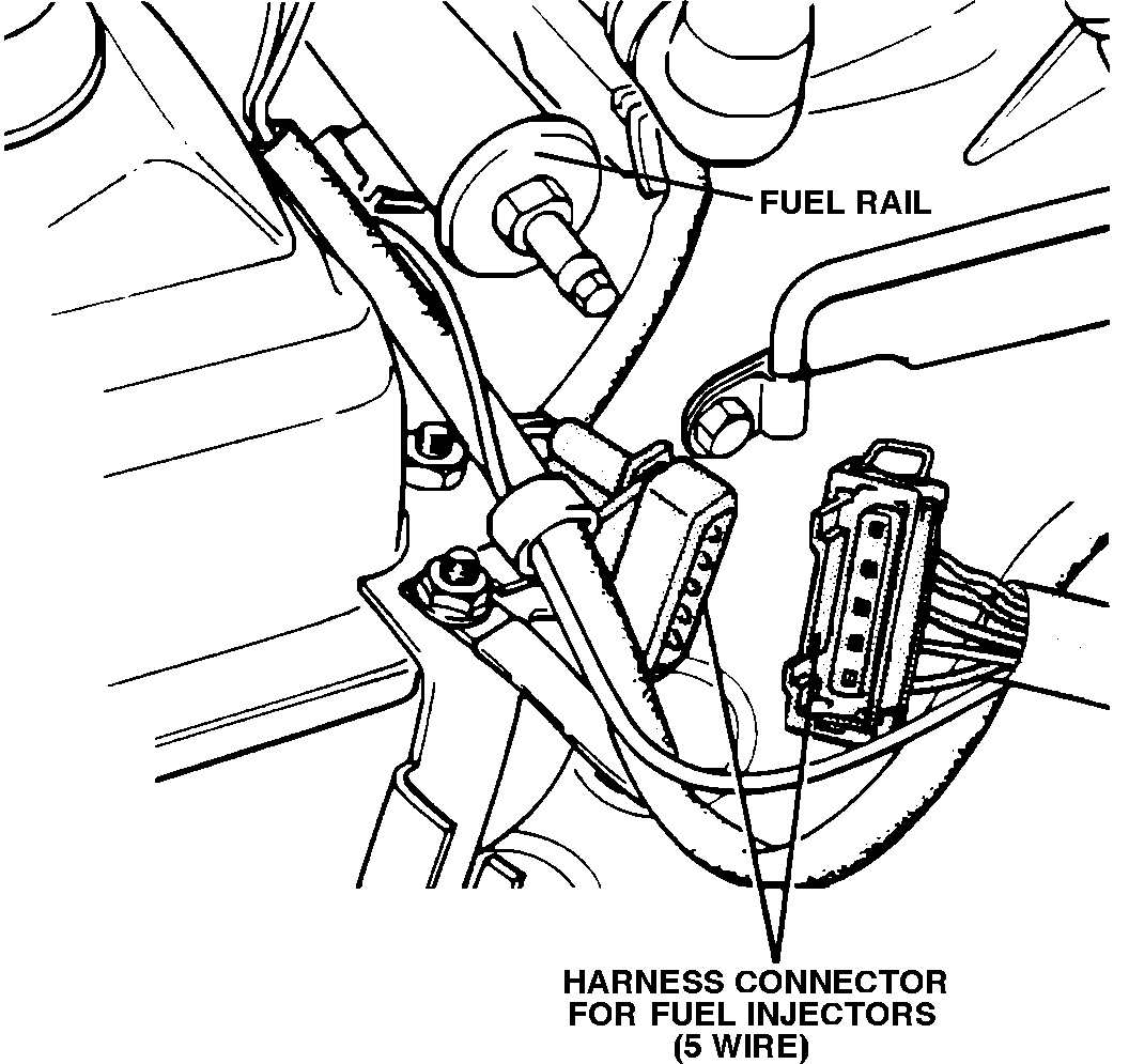
Digifant I Injector Harness Connector
pic 5
- Turn ignition switch "OFF". Disconnect the multimeter. Disconnect the fuel injector main harness connector near the fuel rail.
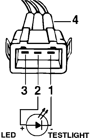
Digifant I Coil Testing
pic 6
- Connect an LED test light between terminals 1 and 2 of the power stage harness connector.
- With the ignition switch crank the engine briefly, then turn ignition switch "OFF".
The LED light must flicker.
- If the LED test light does not flicker, the Camshaft Position (CMP) Sensor, the Motronic control unit, or the wiring may be defective.
- If the test light does flicker continue.
- With the ignition "OFF", reconnect the fuel injector main harness connector, coil wire, and the power stage harness connector.
Digifant I Coil Power Stage Connector
pic 7
- Connect a suitable volt/ohm meter between terminals 1 and 15 of the ignition coil.
- Turn the ignition switch "ON".
The voltage at the ignition coil should briefly rise to a least 2 volts, then drop to zero volts after 1 to 2 seconds.
- If the correct results are not obtained replace the ignition power stage.
_____________________________
I realize this is a lot. Let me know what you find.
Take care,
Joe
Images (Click to make bigger)
Tuesday, December 17th, 2019 AT 7:04 PM