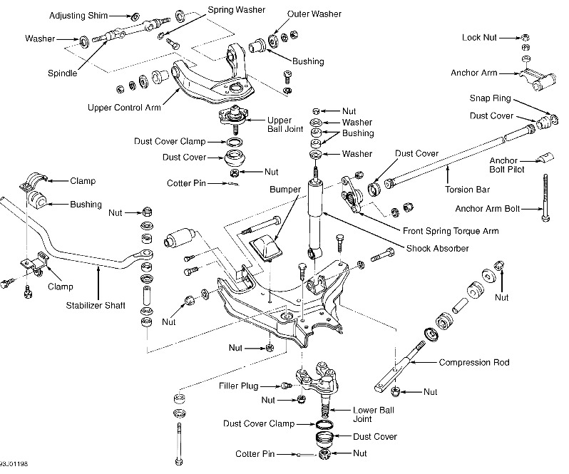
Raise and support vehicle. Remove wheel. Remove shock absorber upper nut. Support lower control arm with floor jack. Remove cotter pin and stud nut from upper ball joint. Separate ball joint from steering knuckle. Remove upper control arm spindle-to-frame bolts. See Fig. 6 or Fig. 7.
Collect all camber adjusting shims. Remove upper control arm, and place in soft-jawed vise. Remove upper ball joint-to-upper control arm nuts and bolts, and remove ball joint.
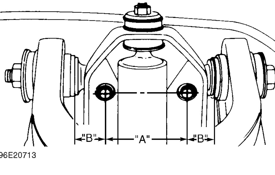
Install upper ball joint. Install upper control arm in vehicle with camber shims installed. Tighten upper control arm spindle-to-frame bolts to specification. See TORQUE SPECIFICATIONS. After fitting, check dimensions "A" and "B". See Fig. 5. Also, refer to CONTROL ARM & SPINDLE DIMENSIONS.
Install upper ball joint to knuckle. Ensure grease does not contact ball joint tapered areas or knuckle. Install wheel and lower vehicle. Tighten spindle nuts to specification. Refer to TORQUE SPECIFICATIONS. Check riding height "H" of lower control arm. See Fig. 2. See TORSION BAR SETTING DIMENSIONS table under TORSION BAR under REMOVAL & INSTALLATION. Check wheel alignment. For 1995-96 models, see NISSAN-SPECIFICATIONS & PROCEDURES article in WHEEL ALIGNMENT. For 1997 models, see NISSAN-SPECIFICATIONS & PROCEDURES article in WHEEL ALIGNMENT.
A=110mm B=32mm
Images (Click to make bigger)
SPONSORED LINKS
Wednesday, March 26th, 2014 AT 6:46 AM