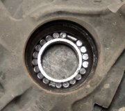
It looks like the hub nut needs to be taken off, then the hub and rotor can come off as an assembly.
DISC & DRUM -1994 Mercury Capri
Page 1 of 1
FRONT BRAKE ROTOR
Removal
1.
Raise and support front of vehicle. Remove wheel. Unstake drive shaft nut tab. Remove and discard drive shaft nut. Separate tie rod end from knuckle.
Disconnect brake hose from strut (if necessary). Remove brake caliper from knuckle, and wire out of way. Remove nuts and bolts holding ball joint and strut to knuckle assembly.
Remove knuckle assembly from ball joint and drive shaft. If binding occurs, use a dual-jawed puller to force knuckle assembly from drive axle shaft.
2.
3.
NOTE:
Hub and rotor are a matched and balanced assembly. Before removing rotor, locate paint or etch mark indicating proper hub-to-
rotor alignment. If marks are not visible, mark hub and rotor for assembly alignment. Failure to properly align hub and rotor can
result in an imbalance condition.
4.
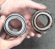
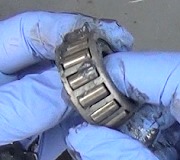
Using a puller, separate knuckle from wheel hub. Retain original outer bearing preload spacer to maintain bearing preload setting. If replacing bearing, install appropriate spacer to adjust bearing
preload (if necessary). See FRONT WHEEL BEARINGS under REMOVAL & INSTALLATION. Scribe match marks on hub and rotor. Remove rotor bolts. Separate hub from
rotor.
Installation
Align reference marks. Install rotor onto hub. Tighten bolts to 33-40 ft. Lbs. (45-54 Nm). Press knuckle and preload spacer into wheel hub. To complete installation, reverse removal procedure. Tighten NEW
axle shaft lock nut to 117-175 ft. Lbs. (159-237 Nm).
1/25/2012
Thursday, January 26th, 2012 AT 5:55 AM