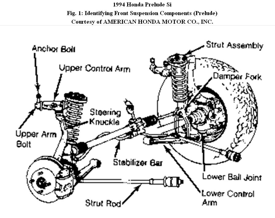
LOWER CONTROL ARM & BALL JOINT
Removal
1. Raise and support front of vehicle. Remove wheel assembly. Remove strut fork and strut rod (radius arm) bolts. Remove nut, bolt and bushings from stabilizer bar.
2. Remove cotter pin from lower control arm ball joint, and remove castle nut. Using puller, separate lower control arm from ball joint. Pull arm down until clear of lower ball joint stud. Remove lower control arm pivot bolt, and remove control arm.
3. Remove steering knuckle. Remove dust boot snap ring, dust boot and external ball joint snap ring.
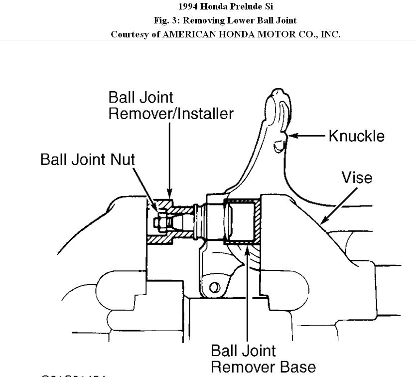
4. Install Ball Joint Remover/Installer (07965-SB00100) Place installer over ball joint stud with large diameter opening facing away from ball joint. Install stud nut.
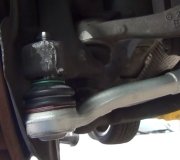
5. Position Ball Joint Remover Base (07JAF-SH20200) with open end over ball joint flat surface. Place assembly in vise. Tighten vise and press ball joint from steering knuckle. See Fig. 3.
Fig. 3: Removing Lower Ball Joint
Installation
1. Position ball joint in steering knuckle. Install ball joint remover/installer on stud end of ball joint with large diameter opening facing ball joint. Position Ball Joint Installer Base (07965-
SB00200) over end of ball joint. Using vise, press ball joint into nuckle.
2. Install ball joint snap ring and dust boot. Using Dust Boot Snap Ring Guide (07974-SA50700), install dust boot snap ring.
3. Reverse removal procedure to install control arm. Use a NEW lower control arm pivot bolt.
UPPER CONTROL ARM
Removal
1. Raise and support front of vehicle. Remove wheel assembly. Remove cotter pin and nut from upper ball joint stud.
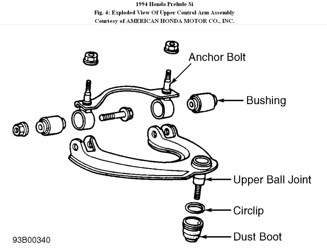
2. Using ball joint remover, separate upper ball joint from steering knuckle. Remove upper control arm anchor bolts-to-body retaining nuts. See Fig. 4. Remove upper control arm. Clamp each upper arm anchor bolt in a vise. Remove upper arm bushings.
Note : There are no service part available for upper arm ball joints.
Installation
To install, reverse removal procedure. Tighten nuts and bolts to specification. Check camber, and adjust if necessary.
Fig. 4: Exploded View Of Upper Control Arm Assembly
Images (Click to make bigger)
SPONSORED LINKS
Monday, February 21st, 2011 AT 4:41 PM