"Cranking" and "turning over" are the same thing, so we do not confuse each other. I posted the wiring diagram for your starting and charging systems. I am supposed to be an electrical specialist, but I cannot follow this diagram with any degree of certainty. To add to the misery, every search for the neutral safety switch brings me back to this diagram, but I do not see any reference to it here.
What wires possibly being backward are you referring to?
Please clarify what happens when you connect the large battery cable terminal on the starter solenoid to the smaller "S" solenoid terminal. Does the starter crank the engine? Do you hear a single, rather loud clunk from the solenoid, but the starter does not spin the engine? Watch what happens to the brightness of the head lights too when you do that.
I am going to have to do this from memory of newer circuits and by starting at the solenoid and working back to the ignition switch. I do not see any reference to an anti-theft system, so that should make diagnosis easier. You must have twelve volts all the time on the large battery cable at the solenoid. The second diagram is the same as the first one, except I added some nifty arrows. The red arrow is pointing to that cable. During cranking, voltage on that terminal must not drop below 9.6 volts. This is usually not a judgement call. It is either well above that or a lot too low. If it drops too much, a corroded cable is one suspect. That corrosion often occurs at the end, under the insulation where you cannot see it.
Twelve volts must appear on the smaller "S" terminal, (longer purple arrow), during cranking. Historically this has been a purple wire on GM vehicles. It goes back to terminal number "6" on the bulkhead connector on the firewall. On the inside, under the dash, that is the shorter purple arrow. This bulkhead connector is a good place to find a corroded pair of terminals due to water dripping on them. These will not be overheated and black because the high current does not go through them long enough to cause that damage. If corrosion is the issue, you will find twelve volts on the inside, under the dash, when the ignition switch is in the "crank" position, but you will not find it under the hood on the other side of the connector. If you have a test light, that will be more accurate for this type of tests than a digital voltmeter, but the meter will be okay too, at least for now.
Rather than trying to figure out what to do at this point, I think we will have better luck if I explain as much of this circuit as possible, then see where that leads you. At the shorter purple arrow on the inside bulkhead connector, two wires are shown there. If you follow the lower one down to the lower right corner of the fuse box, it goes to the "ECM", meaning the engine computer, and it has changed to a purple/white wire. That tells me it is not part of the cranking circuit. It is a twelve volt signal for the computer to do something that it only does during cranking, so it is not part of this problem. The upper dashed wire goes to the ignition switch. Along the way, they show an alternate line for the clutch switch used with manual transmissions. This is the place in the circuit where GM normally puts the neutral safety switch, but I do not see any reference to it here. Follow the dashed line to the upper left terminal in the ignition switch connector.
Analyzing the switch operation is just about impossible unless you have a genius like me to interpret it for you! The first thing to be aware of is the connector, when shown above the switch, must be flipped over to match the switch terminals. That is the two black curved double arrows showing the connector, when flipped over, its terminals will line up with the switch terminals circled in red. I drew a small, pretty double-ended turquoise arrow showing that terminal # 3, (Ign 1), on the connector mates with terminal # 3 on the switch.
To understand the switch operation, the yellow arrow is pointing to a movable contact that's shown in the second lowest position which is "lock". As it moves up to the second highest position, the long black contact, (blue arrow), connects with the white contact, (green arrow). That sends twelve volts to terminal # 3, the Ignition 1 circuit. When it gets all the way up to the top, the "start" position, it's still connected to the white contact, which makes sense. You want the ignition system to be powered up in the "run" and the "crank" positions.
Here is where I got confused and assumed there is a mistake on the drawing. The small dashed red arrow is pointing to a jumper between the "solenoid" terminal and the long black contact, (blue arrow). That cannot be there because as shown, the starter solenoid will be energized when the ignition switch is in the "run" position. It would be cranking non-stop while you are driving. I suspect someone at GM drew it like that for reference when they were making up this drawing, then forgot to remove it in the final version. Regardless, the movable contact, (yellow arrow), is supposed to connect the black contact, (blue arrow) with the "solenoid" terminal, just a fuzz left of the dashed red arrow, to energize the starter solenoid.
I am going to stop here with this great and wondrous explanation because when we work back even further, we are going to get to things that we know are working based on your observation the fuel pump is working. To continue back, follow the long black contact, (blue arrow), to the bottom, then follow the jumper over to the right to the dot, (connection), then up to where it ties to three terminal "2"s. Up in the connector, that is shown as having two red wires feeding those terminals. They typically do that because that circuit handles a lot of current, especially when the heater fan is used on the higher speeds often. Multiple terminals share the load and reduce the incidence of them burning up.
I hope this makes sense. I drew this up in MS Word where I can zoom it so it is easier to read. I think you can get by with the first diagram with no arrows on it, then use the second drawing to see what the arrows are pointing to. Basically what we need to see is twelve volts on the purple wire when the ignition switch is in the "start" position.
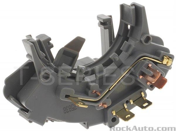
As I mentioned a pile of times, I cannot see where the neutral safety switch comes into the circuit. Typical for GM, it would be where the "clutch switch" is in the circuit. It is simply listed as "in the steering column", but I cannot find a drawing to show it is actual location. The third photo is of the switch assembly so you have an idea of what you're looking for. I have seen these mounted on or near the firewall at the base of the steering column, and that would make more sense, even though the description is confusing. Time listed to replace it is only 0.4 hours, so it is not that hard of a job. If you find the switch, look for twelve volts coming in on the yellow wire when the ignition switch is in the "crank" position, and twelve volts coming out on the purple wire.
If you have not noticed already, there is no starter relay in this circuit. That really surprises me because the starter solenoid can draw up to 20 amps. That is asking a lot of the tiny contacts in the ignition switch. A lot of import cars also do away with the relay and just use the ignition switch, but with smaller engines and smaller starters, those do not put such a heavy load on the ignition switch. Here, this is another reason to have two red wires feeding twelve volts to the ignition switch.
See how far this gets you. I will be back tomorrow to see how much wondrous progress you made.
Images (Click to make bigger)
SPONSORED LINKS
Friday, May 18th, 2018 AT 7:00 PM