Using a voltmeter is easy to use once you know how, this device is inexpensive and is available on Amazon starting at $20.00 (US). This guide outlines how a voltmeter is used in automotive repair applications.
What Does it Do?
A voltmeter is used for advanced checking of electrical circuits compared to the even easier to use test light which checks for power and ground. The voltmeter can confirm the amount of voltage present (either AC or DC), or the ohm's resistance in a circuit or device.
When Do I Need it?
When a check engine, battery or an ABS-transaction control warning light comes on it is telling you an electrical error has occurred. This is where a voltmeter comes in handy by testing supply voltage, sensor resistance values, circuit resistance and resistance to circuit ground. These readings help confirm a problem so repairs can be made.
Let Jump In!
Checking supply voltage, this is used when a system voltage needs to be tested,
let's say the fuel pump is not working and you want to see if you are getting 12
volts at the pump before you try removing the pump from the tank. After finding
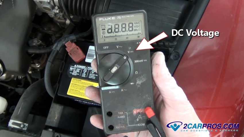
the feed wire color using a wiring diagram, set the voltmeter on DC voltage. Connect
the ground lead of the voltmeter and use the positive probe to pierce the wire,
turn the key to the on position and the voltmeter will display the system voltage.
If wiring diagrams are needed you can ask our experts
to supply you with the information (free), or consult an online resource such as
AllData DIY (pay). After testing seal the pierced wire with silicone rubber and
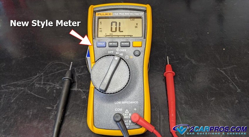
electrical tape. Advanced voltmeters will "self detect" AC or DC voltage which we
show in the images below.
When an engine will not crank
over one of the first tests is to see if the battery has a sufficient surface
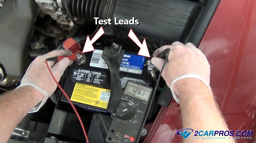
charge. This is easily done using a voltmeter, again set the meter to DC voltage
and connect the negative and positive leads to their respective terminals, the voltage
should be between 12.2 and 12.4 telling you the battery has sufficient surface voltage.
To further test the battery, a load test
need to be performed, this can be done by cranking the engine over and observing
the voltage, it should stay above 10.4 volts, if the voltage drops off quickly the
battery is down on charge or the
battery is bad and needs to be
replaced.
When a battery warning light comes on while driving it means there is a problem
with the charging system. In this case the
alternator output will need to
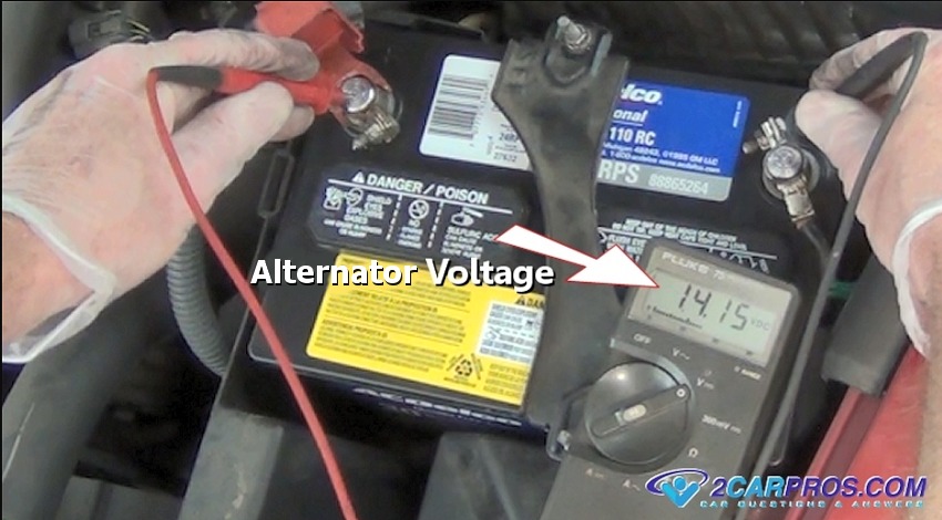
be tested, this is done by starting the engine and allowing it to idle. With
the voltmeter set to DC voltage, connect the leads to their respective terminals,
the voltage should be between 13.7 and 14.2 telling you the alternator is working.
If battery surface voltage is observed the
alternator is probably bad
or there is a blown fuse or
wiring problems.
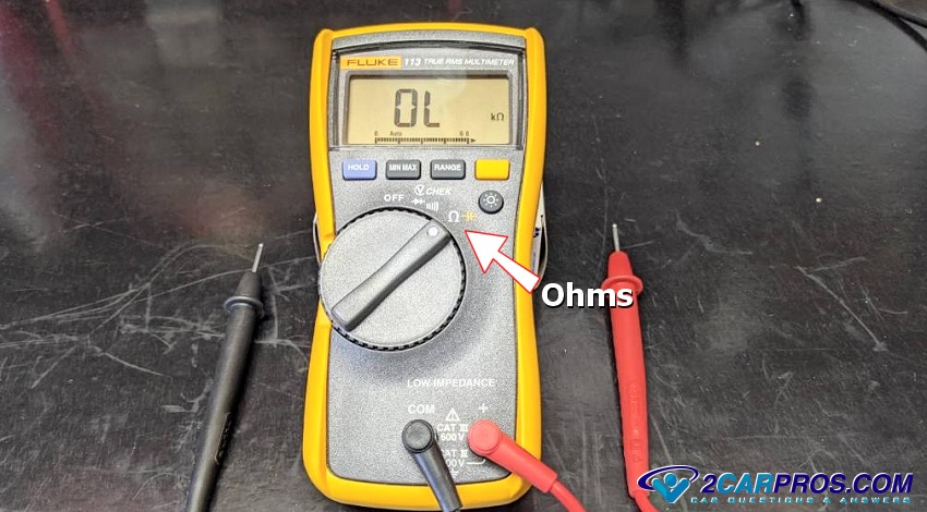
The ohms setting is handy when testing sensors such as an engine coolant, oxygen,
crankshaft and camshaft sensors. Switch the voltmeter selector to Ohms to start
testing.
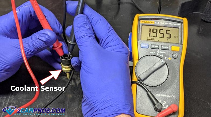
Each sensor will have an acceptable Ohms reading which can confirm the sensor’s
performance. This reading can be obtained by asking one
of our experts (free), in this case we are testing a coolant sensor. This reading
is subject to temperature which is how the sensor works. You can compare the old
sensor to the new sensor readings to confirm the failure, the sensor should be at
a similar ambient temperature for accurate results.
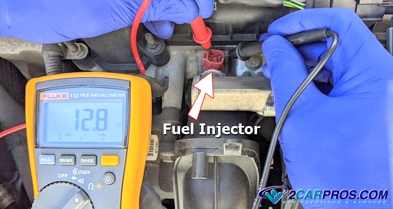
When testing coil based items such as a
fuel injector or
ignition coil a voltmeter
comes in handy. With the meter set on Ohms, attach the meter leads to either side
of the terminals, the meter will display the resistance reading of the coil windings.
If the reading is too low it means the internal coil windings are shorting out.
If the readings are too high the coil has an open circuit, again a new part works
well for comparison.
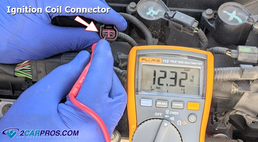
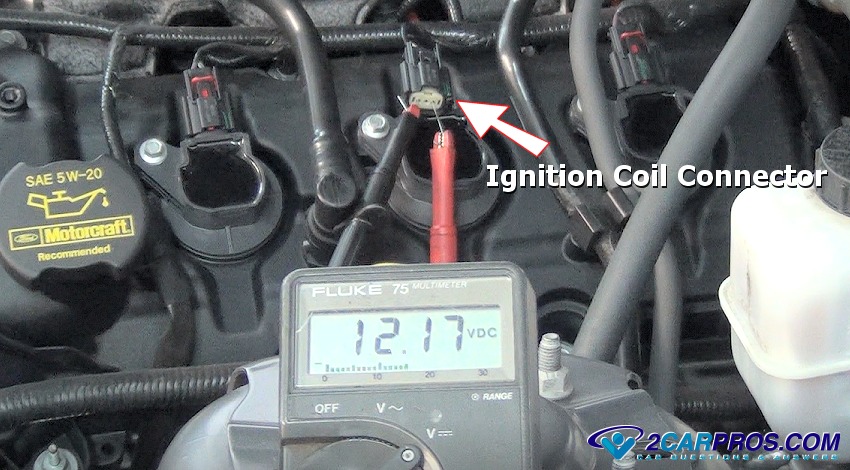
If an engine is not running
a good place to start is to see if the
computer system is powered
up. This is done by checking the system output voltage, remove one of the ignition
coil leads and turn the ignition key on. With the negative lead grounded, probe
the coil wiring connector to monitor the system voltage. If none is present begin
by checking the fuses and
main power relays.
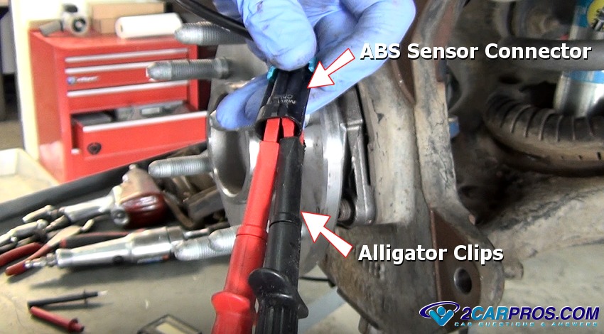
To test voltage of generation devices such as a
crankshaft angle or
ABS wheel speed sensor switch
the voltmeter to millivolts, connect the leads directly to the sensor connector.
In the example below we use alligator clips which are supplied with the voltmeter
in most cases. Once connected, spin the reluctor (bearing hub) or crank the engine
over to check for voltage. If no voltage is present the sensor is bad.
A voltmeter works great for testing the PCM output signals such as ignition coils
or injectors. Connect the voltmeter and switch it to DC voltage, (if the meter doesn't
auto detect). Then crank the engine over, the voltmeter should swing (pulse) between
0 and 12 volts letting you know the computer is working and sending signals to the
coils and injectors.
Questions?
Our certified technicians are ready to answer car repair questions for free. We hope you saved money and learned from this guide. We are creating a full set of car repair guides. Please subscribe to our 2CarPros YouTube channel and check back often for new videos which are uploaded regularly.
Article published 2022-03-08