Alternator wiring diagrams?

Tiny
ALEXBEL
  • MEMBER
  • 1993 OLDSMOBILE ACHIEVA
  • 2.3L
  • 4 CYL
  • 2WD
  • AUTOMATIC
  • 153,000 MILES
There are numbers on the wiring diagram. I have circled them. What do these numbers mean on a wiring diagram? Is it the cross-sectional area of the wires? Is it the diameter? What are the units of measurement? And how do you convert it to mm²?
Monday, April 22nd, 2024 AT 8:26 PM

12 Replies

Tiny
KEN L
  • MASTER CERTIFIED MECHANIC
  • 42,959 POSTS
I can't read it, here are the wiring diagrams from Alldata. They don't tell us the gauge of the wires; can I ask what you are trying to do? Here is what they show us. Check out the images (below).
Was this
answer
helpful?
Yes
No
-1
Tuesday, April 23rd, 2024 AT 10:41 AM
Tiny
STEVE W.
  • MECHANIC
  • 13,001 POSTS
The numbers on that diagram are the metric diameter of the conductor inside the insulation. So a.6 would be.6mm or 22awg.
Was this
answer
helpful?
Yes
No
-1
Tuesday, April 23rd, 2024 AT 6:18 PM
Tiny
ALEXBEL
  • MEMBER
  • 65 POSTS
The wires from the battery to the starter are labeled as 19 BLK. Of course, these wires must have a large cross-section. Maybe the number 19 means the cross-sectional area? Maybe it means 19 mm? (The diagrams are taken from a 1993 US car repair manual).
Was this
answer
helpful?
Yes
No
Tuesday, April 23rd, 2024 AT 8:18 PM
Tiny
ALEXBEL
  • MEMBER
  • 65 POSTS
19 mm2.
Was this
answer
helpful?
Yes
No
Tuesday, April 23rd, 2024 AT 8:20 PM
Tiny
STEVE W.
  • MECHANIC
  • 13,001 POSTS
It is 19mm if you were to cut the wire and measure across the diameter of the exposed copper. The insulation isn't included in the measurement. The images I posted are from the same GM manual. The first three are the definitions for the items in that manual. However, that is not a universal guide as other makes and even other models in the GM line use some different symbols. Others just show the wire color in the diagrams and then use a call out list to give the sizes and others only show the colors. Then there are the various layouts as well, Imports for example use what are known as track diagrams like the attached.
If you want to really learn about how to read them there are multiple videos out there showing the various types and how to read them and what all the symbols are. Also, the diagram for one year may not be the same as another year.
One hugh thing to keep in mind about all wiring diagrams, there may be mistakes on them, that one can catch you really quick.
Was this
answer
helpful?
Yes
No
-1
Tuesday, April 23rd, 2024 AT 9:19 PM
Tiny
ALEXBEL
  • MEMBER
  • 65 POSTS
The diagrams are taken from the book (photo). There are a lot of wiring diagrams in this book. It is unlikely that there are any errors. The diameter of starter wires 19 mm for this car is too much. This cannot be. If we assume that the number 19 means the cross-sectional area, then the diameter will be about 5 mm without insulation. It seems to be realistic. Just in case, let's take one more designation. For example, wire 3Yel5 (or 3PPL6). Assuming that the number 3 is the cross-sectional area in mm2, the diameter is about 2 mm without insulation. Also, realistic. Similarly, you can take other wires, there is the same dependence. What do you think?
Was this
answer
helpful?
Yes
No
Tuesday, April 23rd, 2024 AT 10:12 PM
Tiny
STEVE W.
  • MECHANIC
  • 13,001 POSTS
Believe what you want, I have seen errors in multiple diagrams over the years, both in the OE and redrawn diagrams. 19mm are the main battery cables, which was the design specification and on that vintage would be a heavy cable. It is not any measurement but the diameter. Nothing else.
Do you actually have a problem?
Was this
answer
helpful?
Yes
No
-1
Tuesday, April 23rd, 2024 AT 11:55 PM
Tiny
ALEXBEL
  • MEMBER
  • 65 POSTS
Most cars have battery cables with a cross section of less than 25mm2, which equates to a diameter of less than 6mm. A 19mm diameter would be fine for maybe a WW1 tank! Thanks, I've already made up my mind and don't need anything. Unfortunately, you are wrong.
Was this
answer
helpful?
Yes
No
Wednesday, April 24th, 2024 AT 1:12 AM
Tiny
STEVE W.
  • MECHANIC
  • 13,001 POSTS
Modern cars have the wires based on actual loads, that didn't start happening until the late 90's when companies also started splitting the cable so that one went to the starter and one went to the fuse box. That allowed them to use a smaller main cables that you see on todays cars. The standard for years was a 4/0 AWG cable with some even larger. Those went to the starter main stud which was also the main power feed for the entire vehicle. They used the large size because of the larger engines taking high current to rotate the starter. These days many use 2 or even 3 cables that are between 4 and 6 AWG. That was all in a cost cutting plan, not really sure how that worked out because modern cars have about 4-5 times the amount of wire in them as pre OBDII vehicles and with the increased complexity of networking and security in 2018 and up vehicles is making them much harder to diagnose because of the multiple modules involved in a single system. This has also lead to the use of much smaller wire sizes, where it was common to see 14 AWG for things like taillights now you see a single power feed to a module and then an individual 20 or 22 awg wire coming from the module back to each function in the light.
Was this
answer
helpful?
Yes
No
-1
Wednesday, April 24th, 2024 AT 11:44 AM
Tiny
CARADIODOC
  • MECHANIC
  • 33,752 POSTS
Hi guys. I've been following along to learn new stuff, but I have to add one comment of value. If anyone thinks there are no errors in books and service manuals, shows you haven't been in the business very long. At the dealership I worked for, they got sticky pages every week straight from the manufacturer to stick over pages in their service manuals. Those were to correct mistakes mechanics had found. You could also buy those oem manuals. They were shipped out from one of their training centers. In my case, the nearest one was in Milwaukee. This was also one of the facilities where the instructors took in vehicles that had defied diagnosis by normal means, and it was where service bulletins originated from. They had a couple of large rooms filled with shelves of new service manuals and specialty diagnostic manuals like for ABS and transmissions. What they did not have were those correction pages other than the same stack that got sent to the dealerships. That means if you ordered a manual, you never got any of the correction pages. The only way to get them was to buy them at a dealership auction when one went out of business. There was no attempt to keep them secret. The problem was there was no way to know who bought or currently owned a manual, so there was no way to know where to send the pages.

Most of the time, when I bothered to compare a page I was asked to insert, the mistakes involved incorrect or updated wire sizes, or the wrong terminal number was listed next to a connector. It was not common to find a wire with the wrong colors listed, or going to the wrong place. Often the mistake had nothing to do with the circuitry itself. There might be a designation that this wire was continued on "sheet number 32", for example, but it should have said, "sheet 52". You could find the right page eventually, but in the shop, time is money. That correction page saved time by giving the mechanic the right information.

Related to that, most manufacturers make major and minor changes at the end of a model year. One notable exception is Ford. For those vehicles, it is very common to need to know the production date to get the right parts. Diagrams in the service manual will show two alternatives to part of a circuit, with a qualifier next to them stating, "before" or "after" a certain date. Those changes occurred many times throughout the model year, so it was not practical to reprint manuals or correction pages over and over. So what happens when the manuals are printed and distributed early in the model year, and all kinds of changes take place later?

It gets even more miserable with GM diagrams. If you look on AllData under "Radio" diagrams, where you'll often find me, they'll list the high-end version two to five times. One is "(with PHL)" version. The next choice is, "(with AGN)" version, etc. Who the heck, other than a GM mechanic, is going to know what all those designations mean? Sometimes they're referring to an optional system that isn't on every model. Used to be if you didn't have cruise control, you didn't have steering wheel controls, including remote radio controls. They couldn't just say, "with cruise control". They had to use the sales code used when ordering the vehicle.

Sometimes GM uses a three or four-digit code from the vehicle ID number you have to use when looking for the right diagram. We even run into that when selecting between two or three choices of the same engine size when selecting the right service manual.

In any of these cases, it becomes harder and harder to insure we supply the right diagram. We don't know the car's VIN number, and to keep Google's ratings system happy, we aren't supposed to ask which options are on the vehicle, or even which engine size, when it isn't specified. We're supposed to post all of the diagrams for all of the options. Much of that is for the benefit of others researching the topic, but they have different options from what the original person listed. It takes me from five minutes to a few hours to find and copy the diagrams to answer a question, then to format them into a format that can be uploaded. Then we have to try to figure out how to tell the person how to select the right ones. With all these variables, you can be sure there are going to be differences between the diagram and what's on the vehicle.

I should point out too that most aftermarket manuals such as those from Haynes and Chiltons do an extremely poor job with electrical information. That is in part because they are designed for competent do-it-yourselfers, and those people generally don't do much of their own electrical diagnosis. OEM manuals are the best choice by far for that. All of them will have a few pages in front of the electrical section that lay out all the information you're looking for. I used to find Chrysler's wiring designations the easiest to understand, but it looks like they've switched to copying GM's system. I find those very confusing, but all I have to remember is a "3" is smaller than a "5". I don't need to know a wire's gauge or diameter to diagnose a problem, and if I replace a corroded section, all I have to do is find a replacement of the same gauge.

If you use an online service manual service like AllData, their older diagrams were just scanned out of the original service manual, but again, with no correction pages. On their newer diagrams, they often leave out a lot of connectors. They have their own design for drawing diagrams that can be quite useless, and in many cases, easier to follow.

As a point of interest, for my '72 Challenger, 100 percent of the electrical diagrams fits on just two pages in the service manual. Today you can find from 200 to over 400 pages just for the Electrical section, and almost all are on DVDs with no direct links to the next place. These have produced new highs in misery and frustration. You have all the information, but it's impossible to find it.

I know I didn't help answer any question, and I didn't mean to stick my nose in your conversation, but I just couldn't ignore the misbelief there are no mistakes in service manuals.

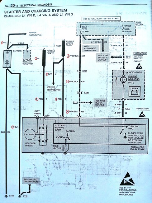
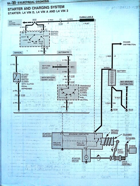
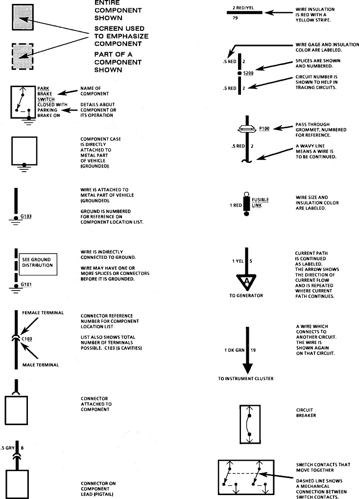
It occurred to me to look for this information for you. I found there's three choices for the 2.3L engine to select the right service manual. You have to use one letter from the VIN. Then, under general electrical repair, there's 15 articles, and within one of them, I finally found a subsection with the three pages I posted below. These would be the same in all GM manuals, regardless of engine size and options. I'm sorry that they show up too small to read. What I do is copy and paste them into a typing program, like MS Word, where they can be expanded. If you don't know how to do that, I can describe the steps, or I can try to cut them up, then expand each part for you.

I'll step back and let Steve continue with his wondrous wisdom. Holler if you need me.
Was this
answer
helpful?
Yes
No
-1
Wednesday, April 24th, 2024 AT 7:19 PM
Tiny
ALEXBEL
  • MEMBER
  • 65 POSTS
I merely asked what these numbers (.5, .8, 1, 3, 5, 8, 19) mean on the 90's automotive wiring diagrams published by General Motors Corporation for all GM vehicles in millions of copies. A person with a minimal knowledge of electrical engineering will easily realize that these designations cannot be diameters. I am not in the US and to repair my car I sometimes have to figure out some of the faults myself. I don't know American standards, but through arithmetic I have determined that these numbers mean the cross-sectional area of the wire in mm2. I was looking for cables from the battery to the starter (19mm2). And I found them. I won't be able to buy them, but I will find similar ones. You can look up what the cross section of these cables are to check. Here are the links:
https://www.gmpartsgiant.com/parts/gm-cable-12157227.html?vin=1G3NL5438PM025097&make=Oldsmobile&model=Achieva&year=1993&submodel=&extra1=&extra2=&filter=()
https://www.gmpartsgiant.com/parts/gm-cable-12157233.html?vin=1G3NL5438PM025097&make=Oldsmobile&model=Achieva&year=1993&submodel=&extra1=&extra2=&filter=()
https://www.rockauto.com/en/moreinfo.php?pk=1110616&cc=0&pt=2500&jsn=274
Best wishes for success.
Was this
answer
helpful?
Yes
No
Wednesday, April 24th, 2024 AT 9:59 PM
Tiny
CARADIODOC
  • MECHANIC
  • 33,752 POSTS
Dandy. That's the original reason I started following your question. I wanted to know the same thing as nothing common made sense. Why they would use such a system is beyond me.

I know this won't help, but for the benefit of others who might be interested, Ford puts a two or three-digit number next to each wire, then they put the color separately. In one diagram I was just using, the wire leading to a switch is number 238, and the wire leaving that switch is number 866. There's no rhyme or reason other than to show that every wire not labeled 238 is different than 238. Duh?

Chrysler's appear to be the most confusing until you understand them. A typical example would be "L18 12DB/RD". "A" circuits start out at the battery positive post, "Z" circuits end at ground, then each system gets its own first letter in between. "L" is for lighting circuits. The "18" is the circuit number to just differentiate it from other "L" circuits. "12" is for 12 gauge, and the color is dark blue with a red stripe, or "tracer". In their world, that wire might splice off into two or more smaller wires labeled L18 14DB/RD. The "L18" tells you it's the same wire with no switches or fuses in between.

Imports have their own systems too that add more confusion. Anyway, I'm happy you found the answer, and thank you for sharing it with us. Please come back to see us with your next question.
Was this
answer
helpful?
Yes
No
+1
Friday, April 26th, 2024 AT 5:24 PM

Please login or register to post a reply.

Sponsored links