Welcome to 2CarPros.
If you can hear the motor running, chances are the linkage has come disconnected on the wiper motor. There is a manufacturer's recall on the ball joint corroding, causing excessive bushing wear, and coming disconnected. Here is the recall and the procedures for repair. Keep in mind, if this is the problem, and most likely it is, it will be repaired for free by a Mitsubishi Dealership. Here is what needs done. The attached pics correlate with this recall and repair instructions. I'm adding this so you have the recall info, and if the vehicle has a reconstructed title, it won't be covered. It's just in case you need to do the work.
_______________________________________
OUTLANDER SPORT WINDSHIELD WIPER LINK - SAFETY RECALL CAMPAIGN - REVISED
image
SUBJECT:
OUTLANDER SPORT WINDSHIELD WIPER LINK - SAFETY RECALL CAMPAIGN - REVISED
No: SR-18-004REV
DATE: March 2018
MODEL: 2011-2016 Outlander Sport / RVR
CIRCULATE TO:
[ X ] GENERAL MANAGER
[ X ] PARTS MANAGER
[ X ] TECHNICIAN
[ X ] SERVICE ADVISOR
[ X ] SERVICE MANAGER
[ X ] WARRANTY PROCESSOR
[ X ] SALES MANAGER
This bulletin supercedes SR-18-004, to correct the wiper motor part number on page 8, and to clarify that Part # 8250B137 cannot be used on Outlander Sport Windshield Wiper Motor recall.
PURPOSE
This bulletin provides directions for replacing the windshield wiper link rod.
BACKGROUND
In the event that water drops down through the back side of the front deck garnish (the body piece between the hood and windshield), the front wiper link ball joint may experience excessive moisture and corrode. If this occurs, the resin case of the ball joint will wear prematurely due to the ball joint corrosion and the wiper link may ultimately separate causing the windshield wipers to stop operating.
If wiper link separation occurs, the windshield wipers will become inoperative which could reduce driver visibility under certain conditions and increase the risk of a vehicle crash.
AFFECTED VEHICLES
2011 - 2016 Outlander Sport / RVR
image
REQUIRED OPERATIONS
Before starting this campaign procedure, CHECK THE WARRANTY SUPERSCREEN to verify if the vehicle is an affected VIN for this campaign and that this campaign procedure has not already been completed. You must also check the Superscreen for any open SR-16-010 (C1611Z or C1612Z) campaign. To improve customer satisfaction and to prevent the customer from having to return for a separate repair, you must complete any open SR-16-010 campaign at the same time as this campaign. The labor allowance for SR-16-010 has been reduced to encourage the completion of both campaigns at the same time. Portions of SR-16-010 have been incorporated to enable a smooth completion of both campaigns; however, you must make separate claims for SR-16-010 and SR-18-004.
REQUIRED EQUIPMENT
Precision Flathead Screwdriver
Ornament Remover (Trim Stick)
Bent Nose Pliers (45 Degrees)
19 mm Socket
Adjustable Wrench
Slip Joint Pliers
Straight Edge / Ruler
Hose
Scissors
Pry Bar
Masking Tape
Marker
WIPER LINK ROD ASSEMBLY REPLACEMENT PROCEDURE
image Do NOT mix old parts with new parts.
ImageOpen In New TabZoom/Print
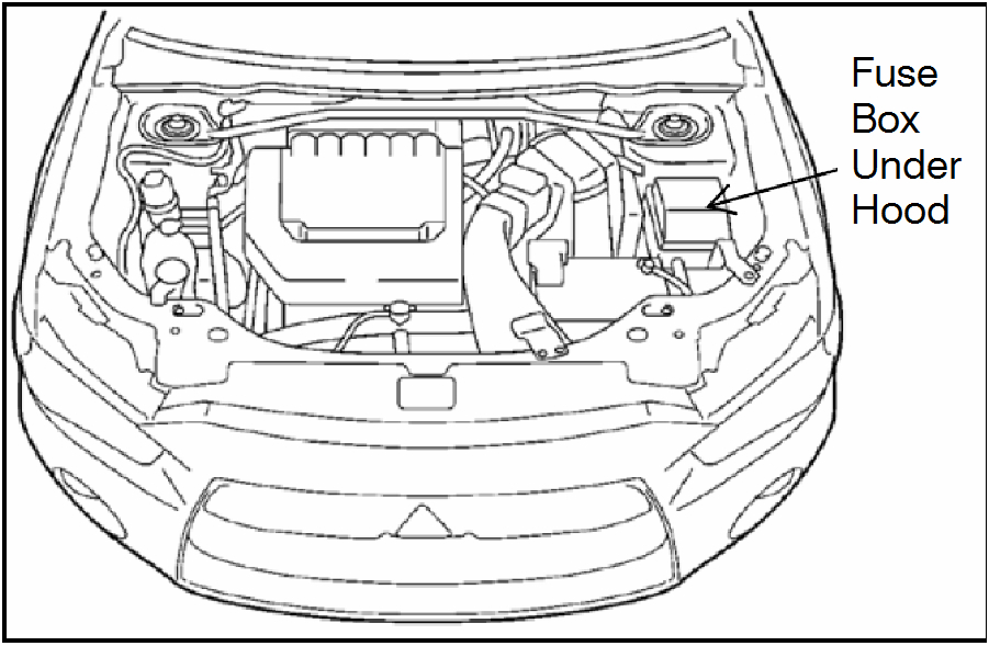
Obtain the Fuse Remover from the engine compartment fuse box.
ImageOpen In New TabZoom/Print
Open the hood.
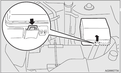
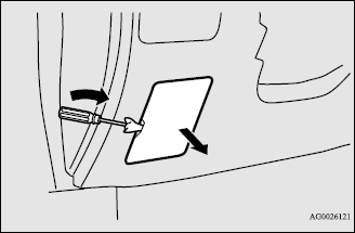
Unlock the fuse box cover by pushing on the lock lever.
ImageOpen In New TabZoom/Print
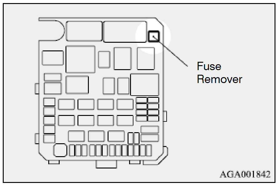
Remove the Fuse Remover.
ImageOpen In New TabZoom/Print
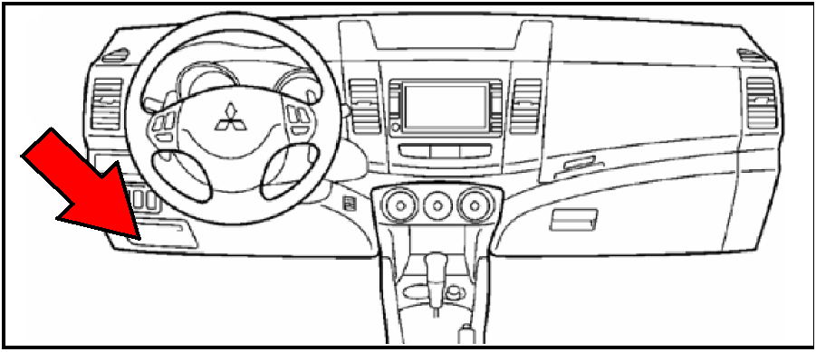
Locate the passenger compartment fuse lid.
ImageOpen In New TabZoom/Print
Remove the passenger compartment fuse lid.
ImageOpen In New TabZoom/Print
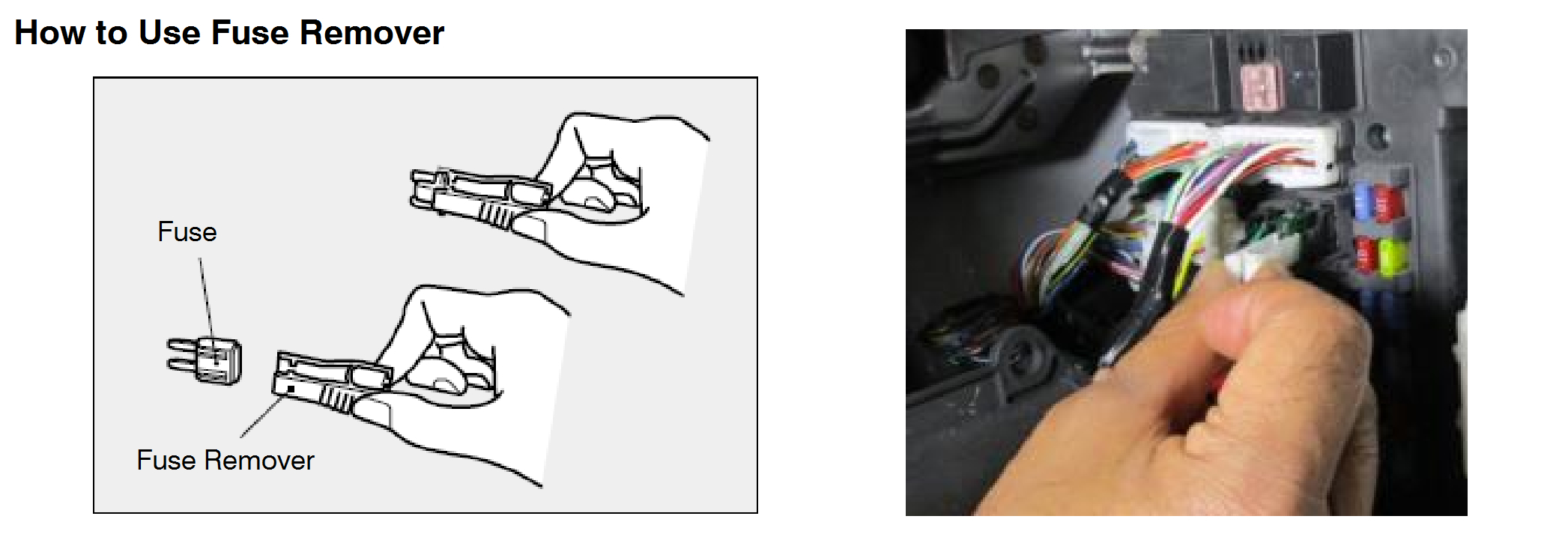
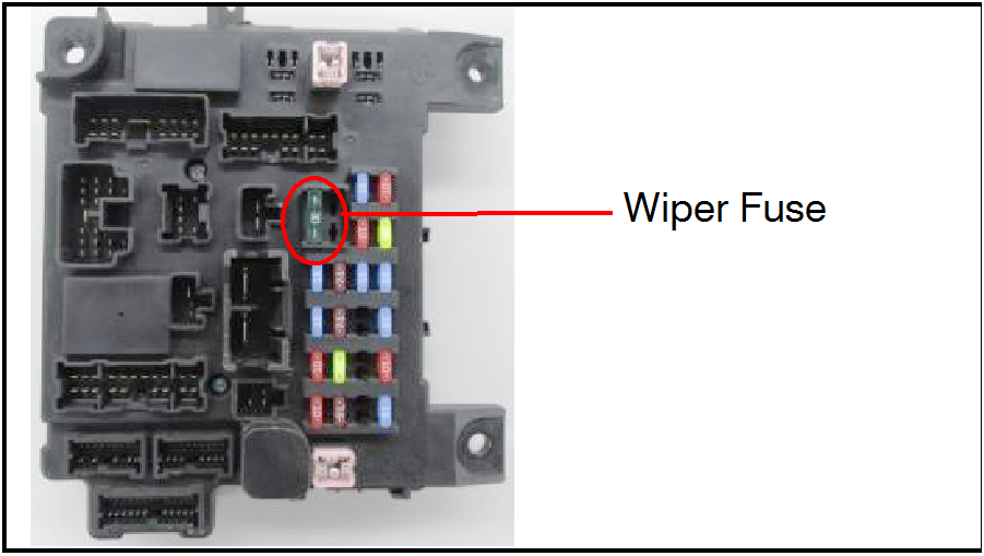
Using the Fuse Remover, locate and remove the green (30 A) Wiper Fuse.
Refer to “How to Use Fuse Remover” instructions below.
ImageOpen In New TabZoom/Print
image A Fuse Remover MUST be used to remove fuses. Use of other tools such as pliers can potentially result in thermal incidents.
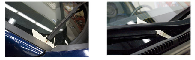
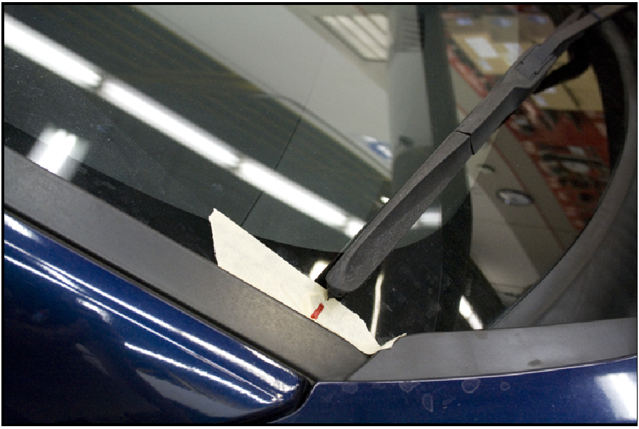
IMPORTANT: Before marking the windshield wiper positions, lift the wiper blade from the windshield and set it back down to ensure that they are resting in their intended positions.
IMPORTANT: Use a fender cover, towel, or similar accessory to protect the fender.
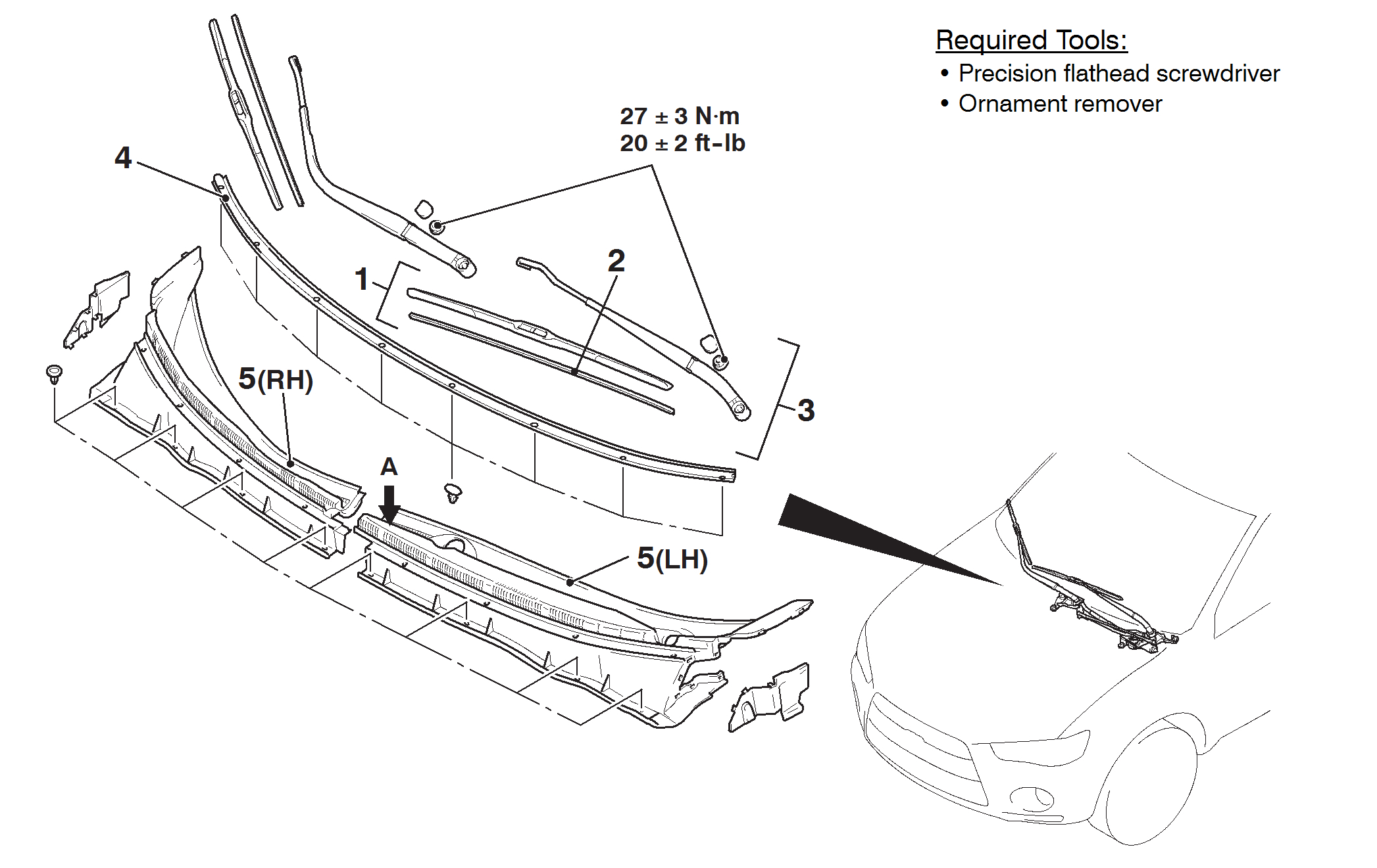
Attach masking tape to the windshield and mark the wiper blades' positions as shown.
ImageOpen In New TabZoom/Print
Remove the wiper arm blade assemblies.
ImageOpen In New TabZoom/Print
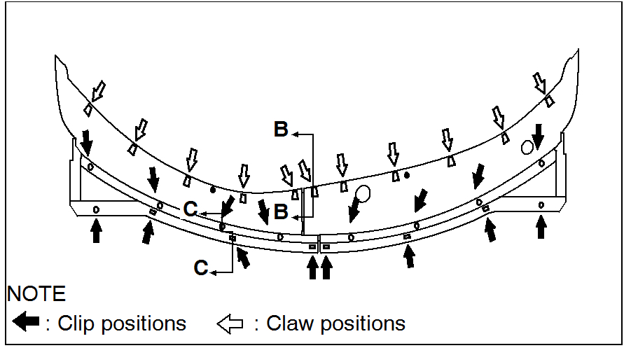
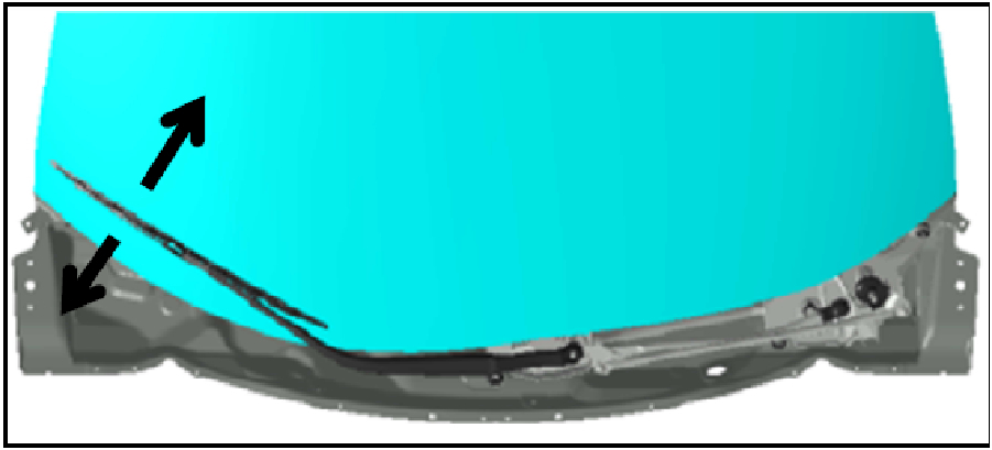
Remove front deck garnish.
ImageOpen In New TabZoom/Print
Remove the passenger side hood rear weatherstrip from the deck garnish.
NOTE: Do not remove the driver side hood rear weatherstrip from the deck garnish (for easier reassembly).
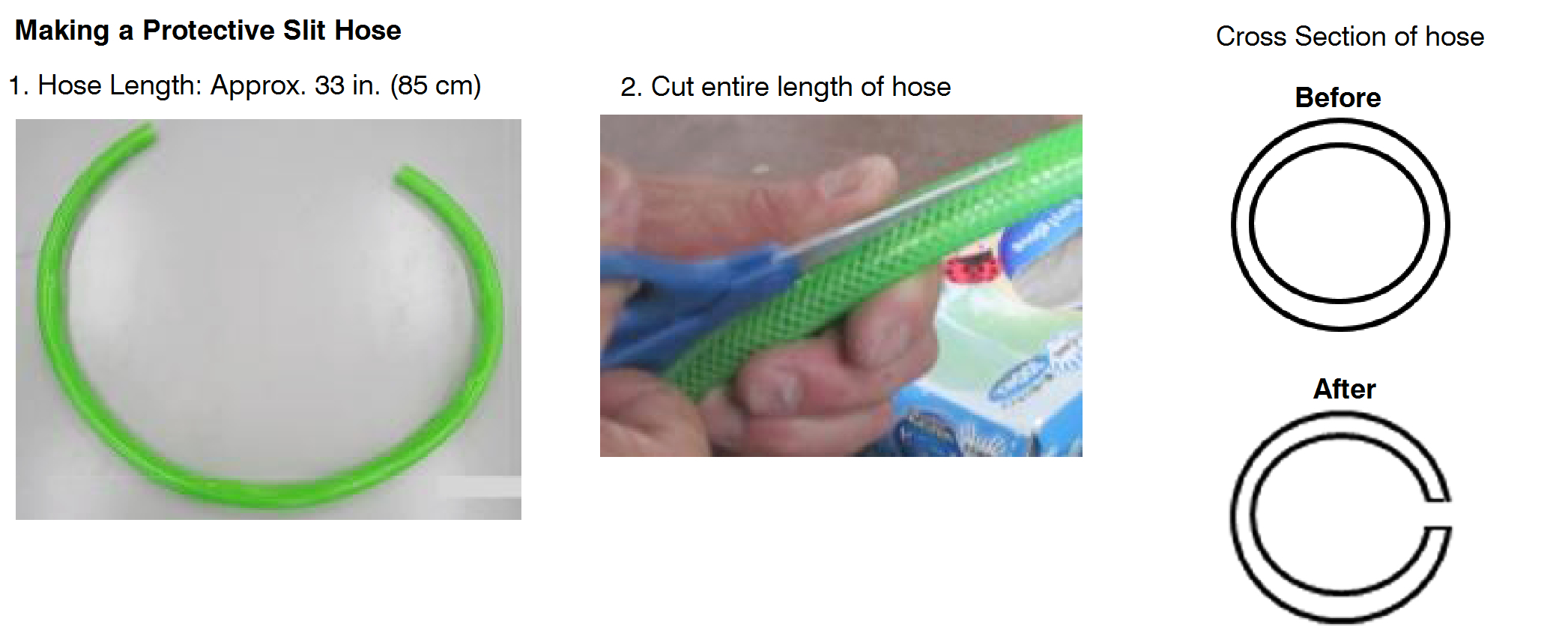
Protect the windshield with a protective slit hose.
Make a protective slit hose as shown below.
ImageOpen In New TabZoom/Print
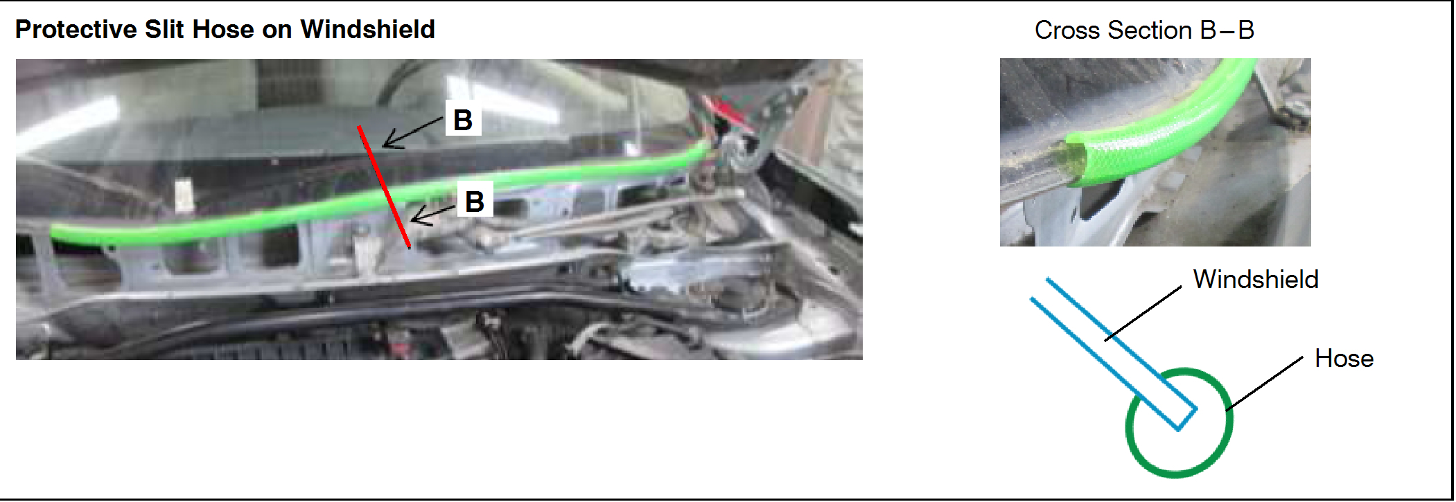
Cover the edge of the windshield with the protective slit hose.
ImageOpen In New TabZoom/Print
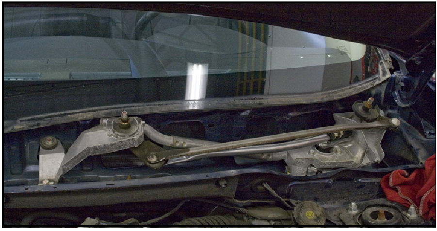
Unbolt the wiper link assembly, disconnect the wiper motor connector, and remove the wiper link assembly from the vehicle.
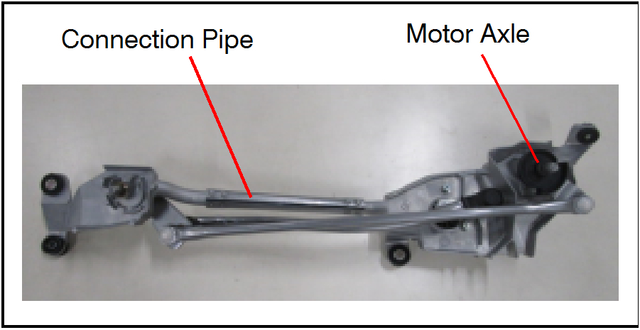
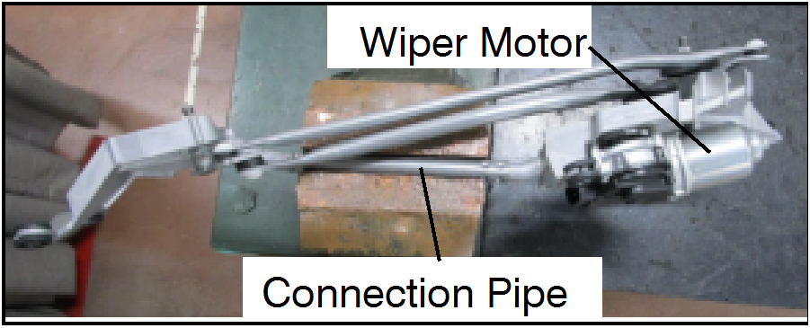
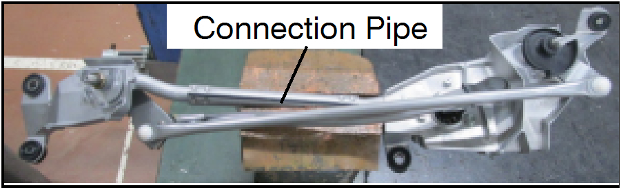
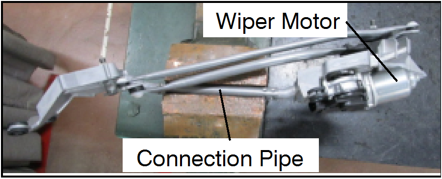
Image Clamp the wiper link assembly at the connection pipe only.
ImageOpen In New TabZoom/Print
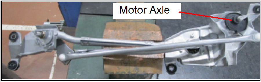
Place the wiper link assembly in a vice with the motor axle pointing up.
ImageOpen In New TabZoom/Print
CAUTION: Clamp ONLY the connection pipe section.
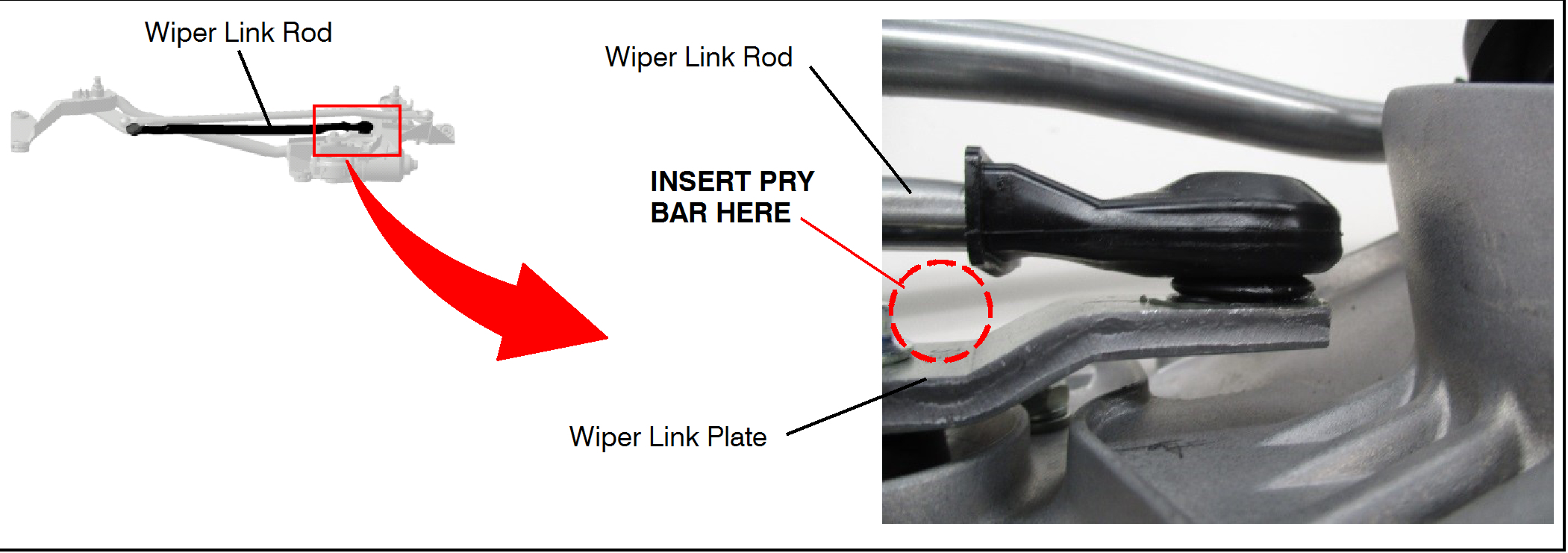
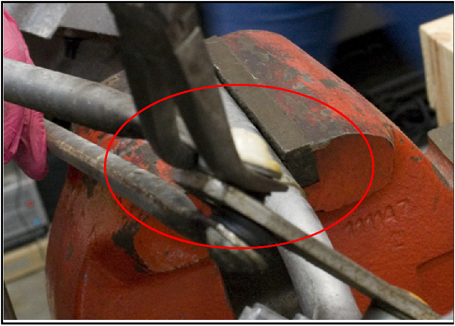
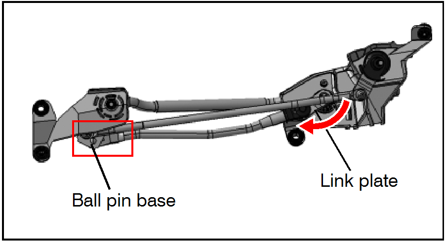
Use a pry bar or similar device to separate the wiper link rod from the wiper link plate.
Insert the pry bar and lift using leverage in area shown below.
ImageOpen In New TabZoom/Print
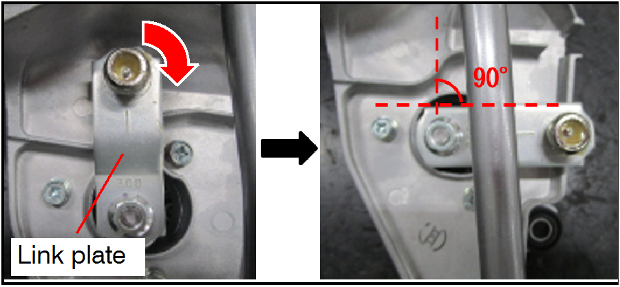
image Turn the link plate slowly to avoid internal damage to the wiper motor.
ImageOpen In New TabZoom/Print
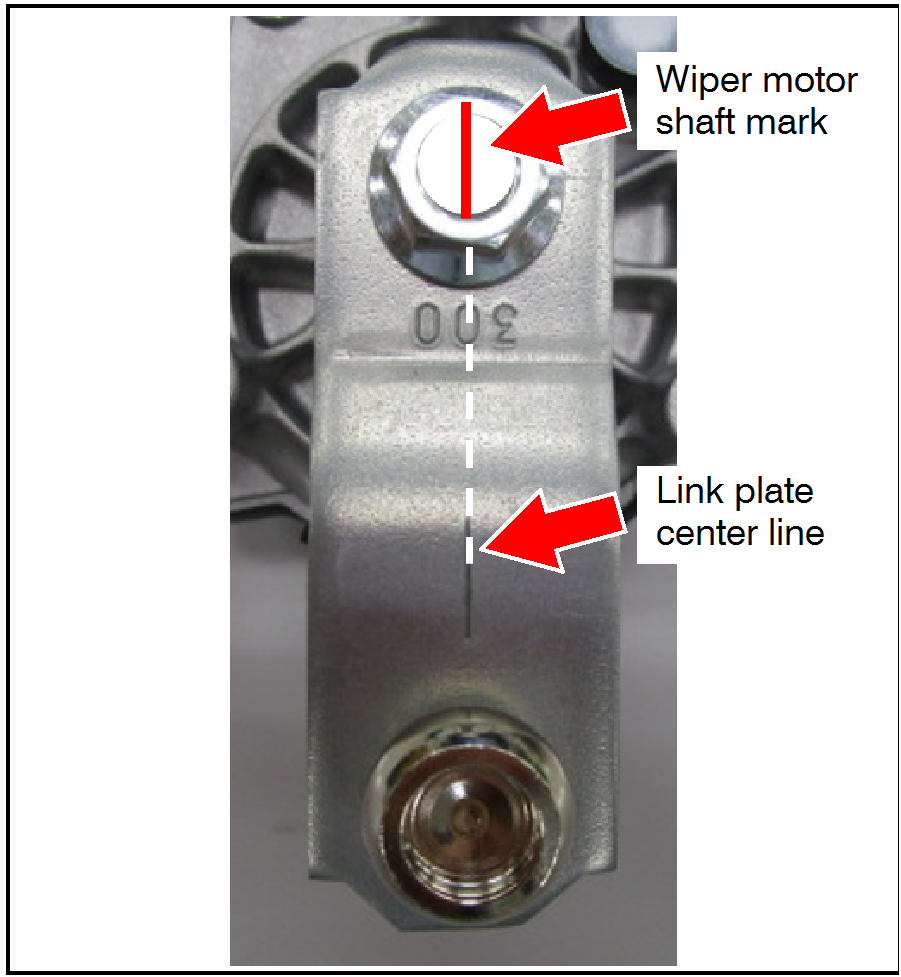
Use a straight edge to line up the link plate center line and the center of the wiper motor shaft, and use a marker to create a visible marking on the wiper motor shaft.
ImageOpen In New TabZoom/Print
Turn the link plate approximately 90 degrees clockwise.
ImageOpen In New TabZoom/Print
For vehicles with recall SR-16-010 open:
Remove and discard old wiper motor.
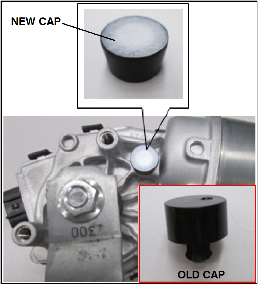
Obtain the new countermeasure wiper motor (part # MW400223). Image
Verify that the new wiper motor has a breathing hole cap with a water proof cloth, as shown.
NOTE: Part # 8250B137 cannot be used on Outlander Sport Windshield Wiper Motor recall. Image
imageOpen In New TabZoom/Print
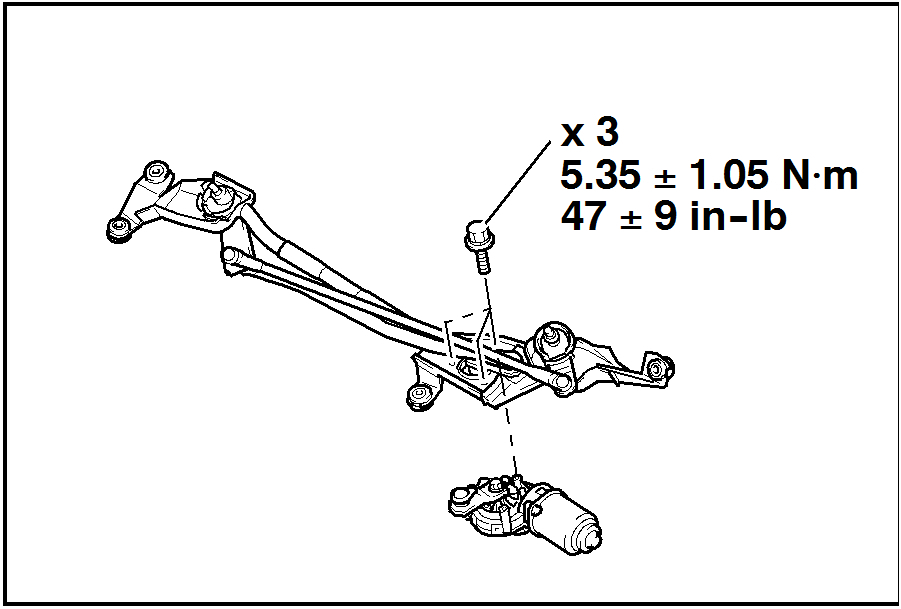
For vehicles with recall SR-16-010 open:
Install the new wiper motor to the wiper link assembly as illustrated, and tighten the 3 bolts to 47 ± 9 in-lb (5.35 ± 1.05 Nm).
ImageOpen In New TabZoom/Print
Hold the link plate in place with an adjustable wrench while loosening the link plate nut.
Remove the link plate and link plate nut.
NOTE: The link plate nut will be reused. Do not discard.
ImageOpen In New TabZoom/Print
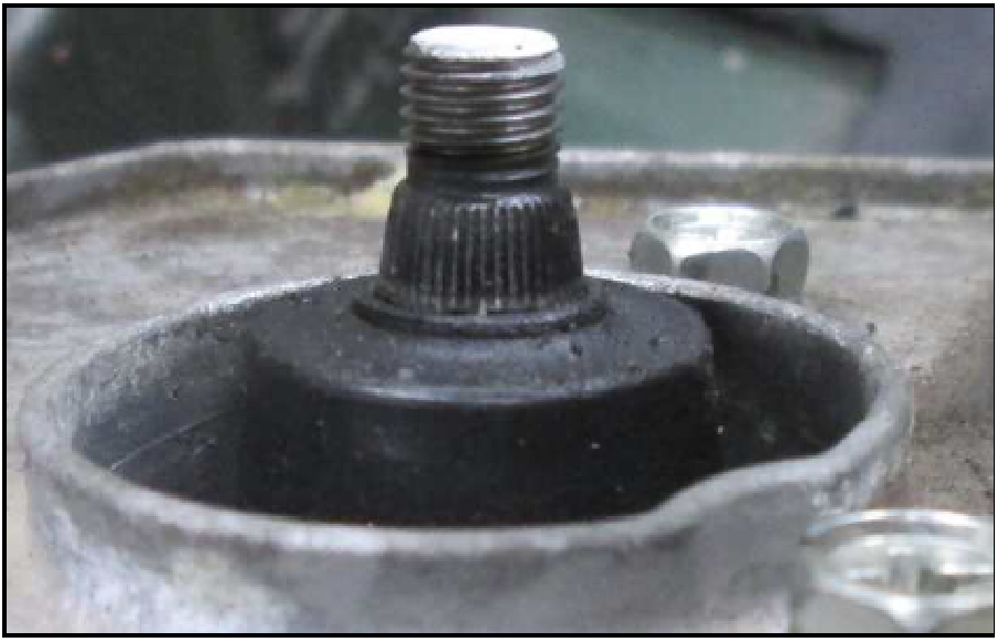
Check the knurling on the wiper motor shaft for any damage and/or debris. Clean off any debris with a clean rag.
Image Clamp the wiper link assembly at the connection pipe only.
ImageOpen In New TabZoom/Print
Rotate the wiper link assembly 90 degrees upward so that the wiper motor is directly visible from the top.
CAUTION: Clamp ONLY the connection pipe section.
ImageOpen In New TabZoom/Print
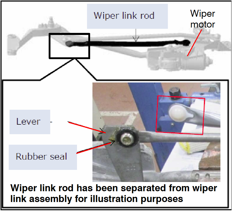
Locate the joint to be separated.
Image Do not remove the wiper motor side joint.
ImageOpen In New TabZoom/Print
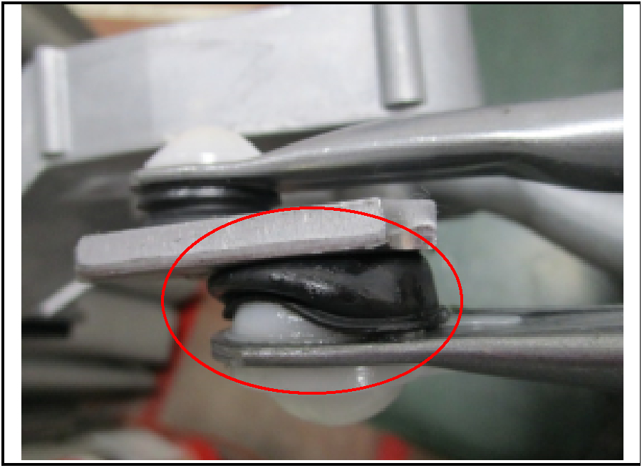
Pull back the rubber seal to prevent damage when performing the following steps.
ImageOpen In New TabZoom/Print
Use bent needle nose pliers to separate the wiper link rod from the wiper link assembly.
ImageOpen In New TabZoom/Print
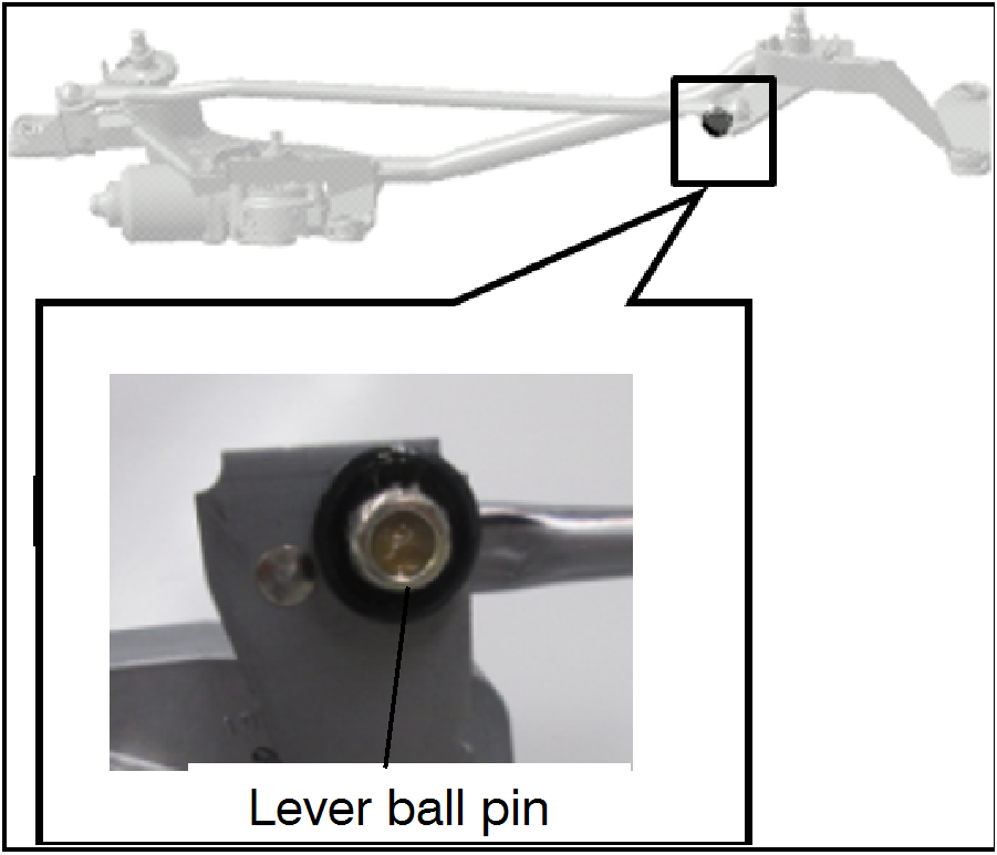
Use a rag to clean dirt and grease off of the lever ball pin and rubber seal.
Image Do NOT install link rod assembly if there is presence of water. If there is presence of water, remove excess water and dry thoroughly prior to re-installation.
ImageOpen In New TabZoom/Print
Verify that the rubber seal is not damaged. If rubber seal is damaged, replace it with a new rubber seal (part # 8251A098).
ImageOpen In New TabZoom/Print
Rotate the wiper link assembly 90 degrees down so that the motor axle is facing up.
CAUTION: Clamp ONLY the connection pipe section.
ImageOpen In New TabZoom/Print
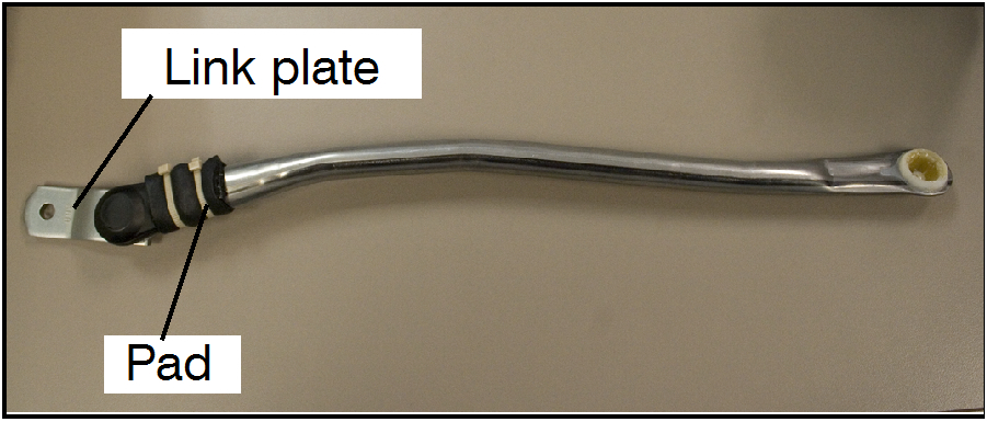
Obtain new wiper link rod (part # 8251A100).
Verify that the new wiper link rod appears as illustrated, complete with pad and link plate attached.
ImageOpen In New TabZoom/Print
Install the wiper link plate to the wiper motor shaft. Make sure that the link plate and wiper link rod are in the correct orientation.
Image Do NOT install link plate in a slanted position.
Image Do NOT damage the pad.
ImageOpen In New TabZoom/Print
Make sure that the wiper motor shaft mark and the link plate center line are lined up. Use an adjustable wrench to hold the link plate in position, to prevent link plate rotation.
Tighten the nut to 12.5 ft-lb ± 1 ft-lb
(17.2 ± 1.0 Nm).
ImageOpen In New TabZoom/Print
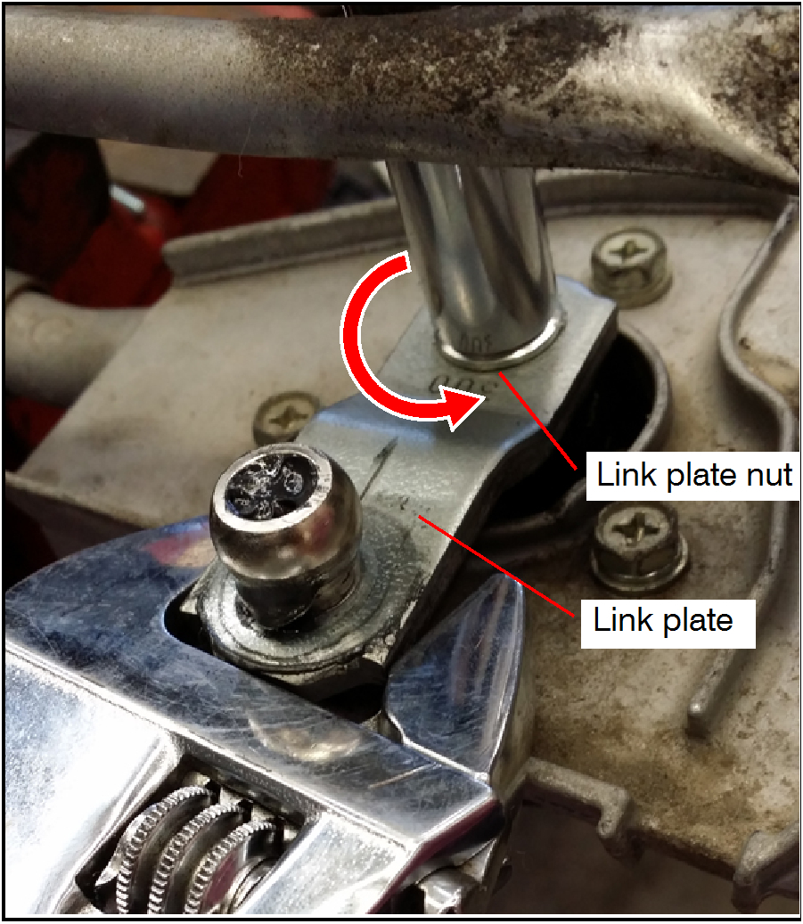
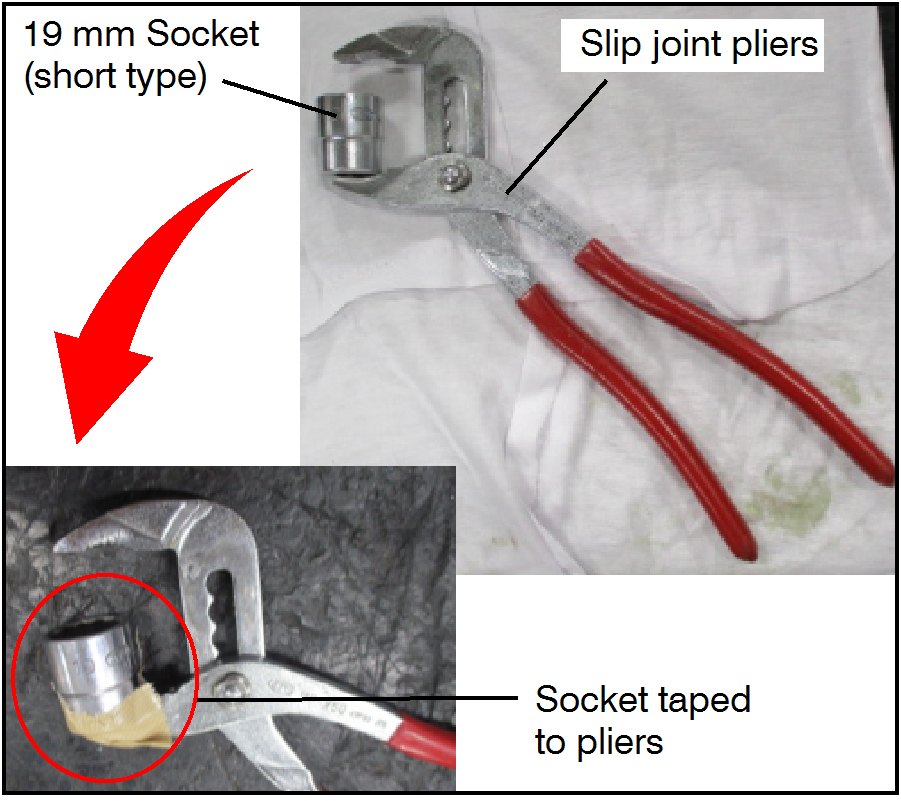
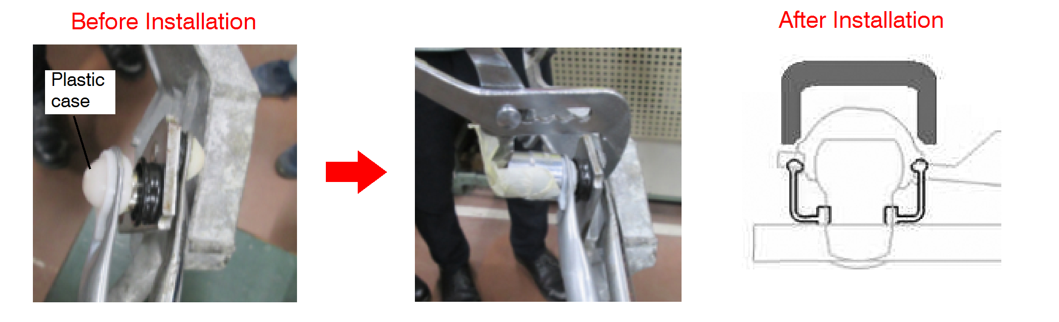
To prevent damage to the plastic case, improvise a tool using a 19 mm socket taped to slip joint pliers as shown.
Image Turn the link plate slowly to avoid internal damage to the wiper motor.
ImageOpen In New TabZoom/Print
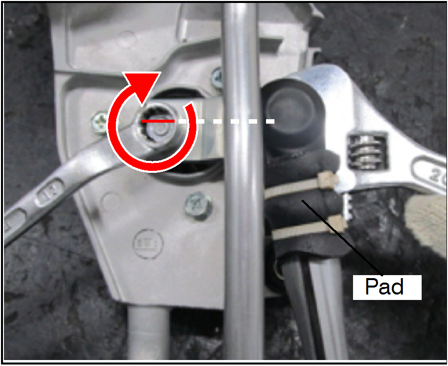
Turn the link plate slowly in the direction shown by the red arrow, so that the ball pin's base is visible (for easier installation).
ImageOpen In New TabZoom/Print
Rotate the wiper link assembly 90 degrees upward so that the wiper motor is directly visible from the top.
CAUTION: Clamp ONLY the connection pipe section.
Install wiper link rod, using the improvised tool, to the lever end that is opposing the wiper motor.
ImageOpen In New TabZoom/Print
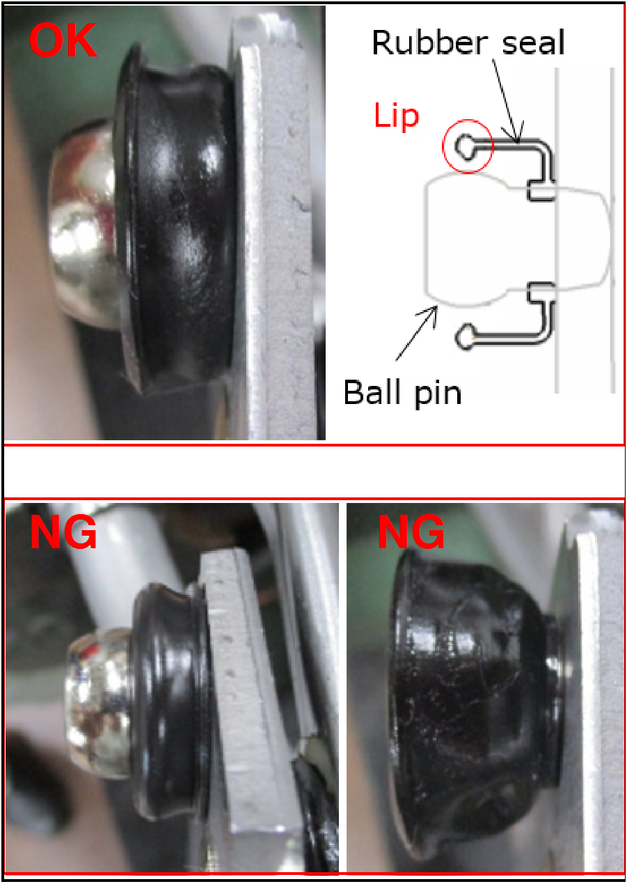
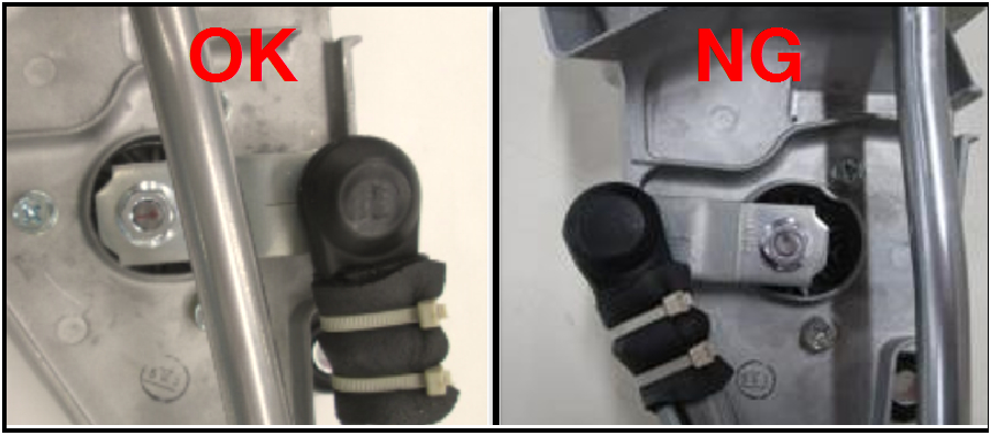
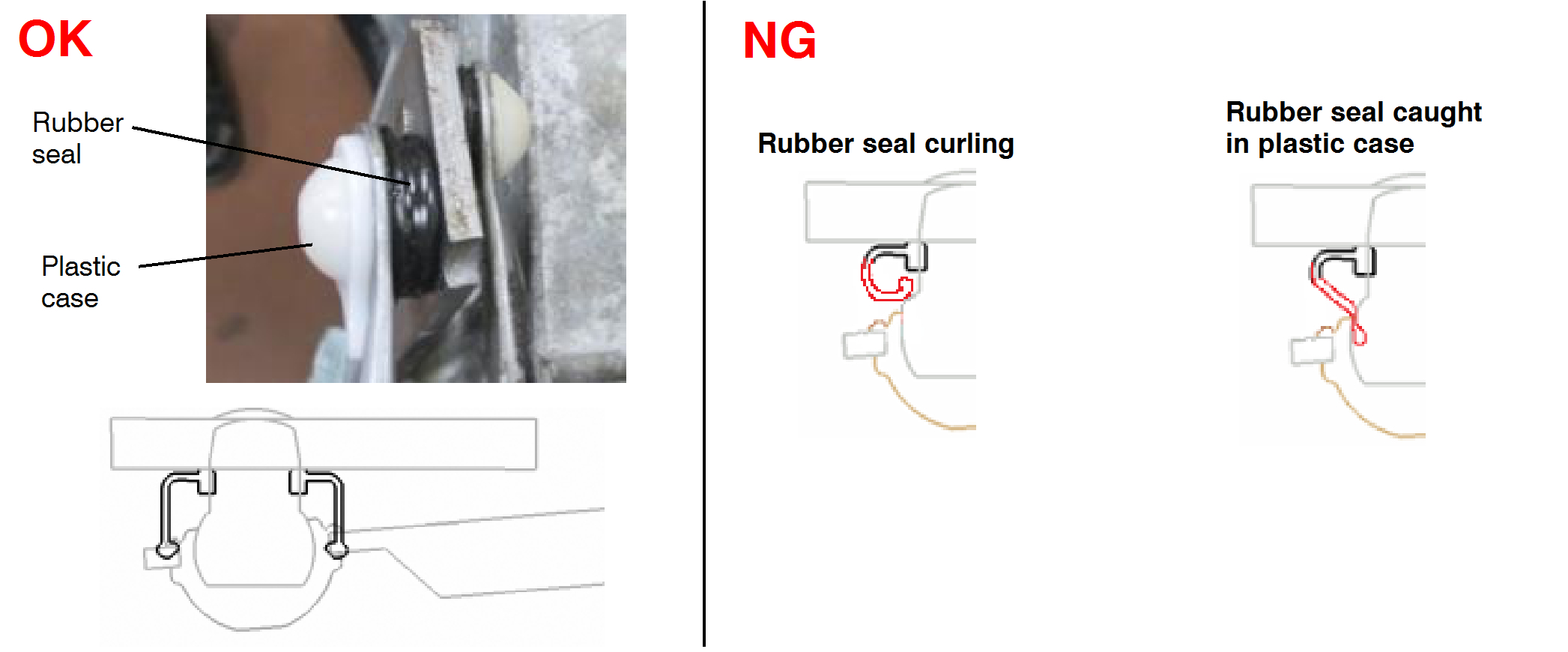
image The rubber seal must be properly seated. Confirm good condition of the rubber seal.
Verify that the rubber seal is properly seated.
Image Confirm that the plastic case is not damaged or cracked.
ImageOpen In New TabZoom/Print
image
Remove the wiper link assembly from the vice.
ImageOpen In New TabZoom/Print
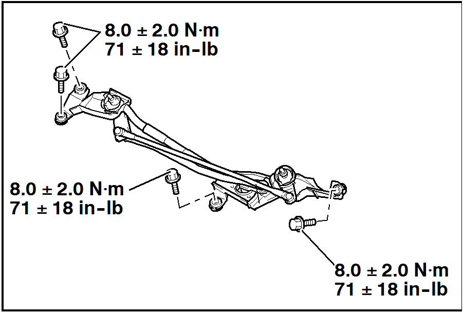
Reinstall the wiper link assembly to the vehicle and connect the windshield wiper motor connector.
ImageOpen In New TabZoom/Print
Torque bolts to 71 ± 18 in-lb (8.0 ± 2.0 Nm).
Image Do not allow any appendages, clothing, or other items to make contact with the wiper link assembly. The wiper may move once the wiper fuse is reinstalled, causing bodily injuries and/or damage to vehicle.
ImageOpen In New TabZoom/Print
Reinstall the Wiper Fuse.
Image
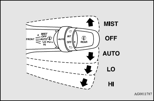
Turn the ignition switch to “ACC” or “ON”.
Switch the windshield wiper switch to “LO” and back to “OFF” to move wiper link to initial position.
Remove protective slit hose from windshield.
ImageOpen In New TabZoom/Print
Install the passenger side wiper arm at the marked position.
Tighten nut to 20 ± 2 ft-lb (27 ± 3 Nm).
ImageOpen In New TabZoom/Print
Confirm wiper operation in wiper “INT” mode for 10 cycles. If either of the following abnormal behavior is observed, perform the appropriate correction.
Abnormal behavior 1: Wiper blade moves up briefly then stops.
Correction procedure: Turn link plate clockwise.
Abnormal behavior 2: Wiper blade moves down briefly during the start of wiper operation.
Correction procedure: Turn link plate counterclockwise.
Image
Remove the passenger side wiper arm.
Reinstall the front deck garnish.
Reinstall hood rear passenger side weatherstrip.
Reinstall the wiper arm blade assemblies to the marked locations.
Tighten nuts to 20 ± 2 ft-lb (27 ± 3 Nm).
ImageOpen In New TabZoom/Print
Verify wiper motor operation by turning the vehicle ignition to “ACC” or “ON” and activate the windshield wipers in “LO” and “HI” positions.
Return the Fuse Remover to the fuse box.
Close the fuse box lid and hood.
ImageOpen In New TabZoom/Print
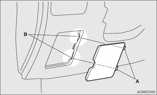
Reinstall the passenger compartment fuse lid by lining up the fuse lid hook (A) with the clamp (B) on the instrument panel and push the lid back in.
_________________________
Let me know what the dealer tells you. Again, you shouldn't have to pay for this repair.
Take care and let me know if you have questions.
Joe
Images (Click to make bigger)
SPONSORED LINKS
Tuesday, April 23rd, 2019 AT 8:18 PM