Welcome to 2CarPros.
This isn't an easy one because the pump is run by the timing belt. It is extensive. However, I will provide the directions. First, we will need to remove the timing belt. The directions I list first are for that procedure. This is the difficult part. The pump is easy and will be listed later in the directions. Also, keep in mind the pump will be replaced midway through the timing belt directions.
_______________________________
Timing belt removal and replacement. Note: I strongly recommend replacing the belt once you have it apart. I don't know if the present one is original, and you won't want to do this again. Also, inspect tensioners and all components related and replace anything that appears worn. The pictures attached correlate with these directions. Also, please feel free to let me know if you run into trouble, need verification, or need help with any part of this procedure. It is vital that you correctly re-time the engine when you are reinstalling the timing belt, so please follow the directions. Also, you will need to drain the coolant prior to doing this work.
______________________________
Timing Belt
Removal
1. Disconnect battery ground cable.
2. Remove air cleaner assembly.
3. Remove radiator upper fan shroud from radiator.
Picture 1
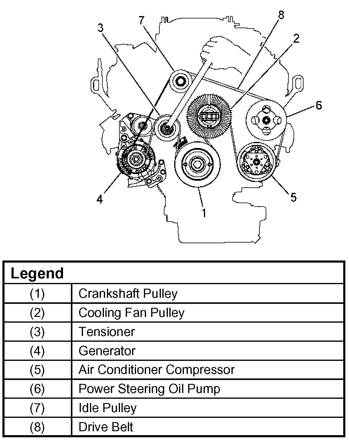
4. Move drive belt tensioner to loose side using wrench then remove drive belt.
5. Remove cooling fan assembly four nuts, then the cooling fan assembly.
6. Remove cooling fan drive pulley assembly.
7. Remove idle pulley assembly.
8. Remove serpentine belt tensioner assembly.
9. Remove crankshaft pulley assembly using J-8614-01 crankshaft holder, hold crankshaft pulley remove center bolt, then the pulley.
10. Disconnect harness connector of right side timing belt cover front side.
11. Remove right side timing belt cover and left side timing belt cover.
12. Remove fan bracket.
Picture 2
13. Remove pusher.
CAUTION: The pusher prevents air from entering the oil chamber. Its rod must always be facing upward.
14. Remove timing belt.
CAUTION:
1. Do not bend or twist the belt, otherwise its core could be damaged. The belt should not be bent at a radius less than 30 mm (1.2 inch).
2. Do not allow oil or other chemical substances to come in contact with the belt. They will shorten the life.
3. Do not attempt to pry or stretch the belt with a screw driver or any other tool during installation.
4. Store timing belt in a cool and dark place. Never expose the belt direct sunlight or heat.
Installation
picture 3
picture 4
picture 5
Note: For correct belt installation, the letter on the belt must be able to be read as viewed from the front of the vehicle.
1. Install timing belt.
Picture 6
1. Align groove of crankshaft timing pulley (2) with mark on oil pump (1).
Align the mark on the crankshaft timing pulley (3) with alignment mark (white dotted line) on the timing belt (4).
Secure the belt with a double clip or equivalent clip.
Note: When timing marks are aligned, No.2 piston will be on Top Dead Center.
2. Align the alignment mark on the RH bank camshaft drive pulley (2) to the alignment mark of the cylinder head cover RH (3).
The camshaft pulley alignment mark should also align with alignment mark on the cylinder head cover.
Picture 7
3. Align the alignment mark (white line) on the timing belt (1) with alignment mark on the RH bank camshaft drive pulley (2) (on the left side as viewed from the front of the vehicle) and put the timing belt on the camshaft drive pulley.
Secure the belt with a double clip or equivalent clip.
4. Align the alignment mark on the LH bank camshaft drive pulley (2) to the alignment mark of the cylinder head cover LH (3).
The camshaft pulley alignment mark should also align with alignment mark on the cylinder head cover.
Picture 8
5. Align the alignment mark (white line) on the timing belt (1) with the alignment mark on the LH bank camshaft drive pulley (2).
When aligning the timing marks, use a wrench to turn the camshaft drive pulley, then set the timing mark between timing belt and camshaft drive pulley and put the timing belt on the camshaft drive pulley.
Secure the belt with a double clip or equivalent clip.
Note: It is recommended for easy installation that the belt be secured with a double clip or equivalent clips after it is installed to each pulley.
6. Install crankshaft pulley temporarily and tighten center bolt by hand (do not use a wrench).
Turn the crankshaft pulley clockwise to give some belt slack between the crankshaft timing pulley and the RH bank camshaft drive pulley.
2. Install pusher and tighten bolt to the specified torque.
Torque: 25 Nm (18.4 ft. Lbs.)
1. Install the pusher while pushing the tension pulley to the belt.
Picture 9
2. Pull out pin from the pusher.
Note: When reusing the pusher, press the pusher with approximately 100 Kg to retract the rod, and insert a pin (1.4 mm (0.055 inch) piano wire).
Picture 10
After release the push rod from the locking pin, the rod projection is approximate 6 mm (0.2362 inch).
3. Remove double clips or equivalent clips from timing belt pulleys.
Turn the crankshaft pulley by six turns and check for timing mark alignment.
3. Install fan bracket and tighten fixing bolts to the specified torque.
Torque: 22 Nm (16 ft. Lbs.)
picture 11
picture 12
4. Install timing belt cover.
Remove crankshaft pulley that was installed in step 1 item 5.
Tighten bolts to the specified torque.
Torque: 19 Nm (14 ft. Lbs.)
5. Install crankshaft pulley using J-8614-01, hold the crankshaft pulley and tighten center bolt to the specified torque.
Torque: 167 Nm (123 ft. Lbs.)
Torque:
M8 bolt: 22 Nm (16 ft. Lbs.)
M10 bolt: 46 Nm (34 ft. Lbs.)
6. Install cooling fan assembly and tighten bolts/nuts to the specified torque.
Torque: 22 Nm (16 ft. Lbs.) For fan pulley and fan bracket.
Torque: 10 Nm (7.4 ft. Lbs.) For fan and clutch assembly.
Picture 13
picture 14
7. Move drive belt tensioner to loose side using wrench, then install drive belt to normal position.
8. Install radiator upper fan shroud.
9. Install air cleaner assembly.
________________________________________________
Now for the simple part. Replacing the water pump.
Water Pump
picture 15
Water Pump and Associated Parts
Removal
1. Disconnect battery ground cable.
2. Drain coolant.
3. Radiator hose (on inlet pipe side).
4. Remove timing belt.
5. Remove idle pulley.
6. Remove water pump assembly.
7. Remove gasket.
Inspection
Make necessary repair and parts replacement if extreme wear or damage is found during inspection. Should any of the following problems occur, the entire water pump assembly must be replaced.
Crack in the water pump body
EC leakage from the seal unit
Play or abnormal noise in the bearing
Cracks or corrosion in the impeller
Installation
1. Install gasket, clean the mating surface of gasket before installation.
Picture 16
2. Install water pump assembly and tighten bolts to the specified torque.
Torque: 25 Nm (18.4 ft. Lbs.)
Tightening order
The tightening order are in the illustrate.
Note: To prevent the oil leakage, apply the LOCTITE 262 or an equivalent, to the arrow marked fixing bolt thread.
3. Idle pulley
Install idle pulley and tighten bolt to the specified torque.
Torque: 52 Nm (38.4 ft. Lbs.)
4. Timing belt
Install timing belt.
5. Connect radiator inlet hose and replenish EC.
6. Connect battery ground cable.
_________________________________________________
Let me know if this helps or if you have questions.
Take care,
Joe
Images (Click to make bigger)
SPONSORED LINKS
Sunday, April 14th, 2019 AT 1:37 PM