When the MIL shows, trouble codes would be stored and code retrieval would assist in understanding what is wrong. Here are the diagnostic procedures. Let me know the code that is retrieved.
SELF-DIAGNOSTIC SYSTEM DESCRIPTION
NOTE: Self-diagnostics for fuel system and ignition system are covered separately in this article.
The fuel injection system and ignition system feature a built-in self -diagnostic function for fault tracing. A common diagnostic unit, located in the engine compartment behind the left strut assembly, interfaces directly with either ECU. The diagnostic unit has a push button, a Red Light-Emitting Diode (LED) and a selector (coding) cable. See Fig. 1 .
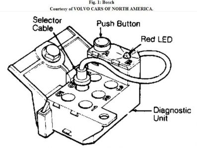
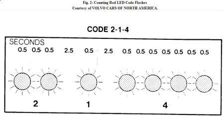
Once the selector cable has been inserted in the correct slot, depressing the button once, twice or 3 times selects from one of 3 control (fault tracing) functions. Faults stored in ECU memory are read via a system of LED flashes. All fault codes have 3 digits, each capable of ranging from 1-to-4 digits. Since all codes have 3 numbers, each code requires 3 series of flashes. For easier reading, a 2.5-second interval separates each digit of the code.
Socket No. 2 in the diagnostic unit is used for fuel system testing. Socket No. 6 is used for ignition system testing.
SELF-DIAGNOSTICS (FUEL SYSTEM)
The fuel system ECU carries out continuous checks. Faults in any of the following functions are stored in system memory.
ï¬ Fuel System ECU internal function
ï¬ Lambda-Sond (Oxygen Sensor)
ï¬ Coolant Temperature Sensor
ï¬ Mass Airflow Meter
ï¬ Battery Voltage
ï¬ Throttle Switch
ï¬ Ignition System ECU and RPM
ï¬ Speedometer
ï¬ Knock Sensor
ï¬ Idle (Speed) Valve
ï¬ Fuel Injectors
ENTERING SELF-DIAGNOSTICS (FUEL SYSTEM) CONTROL FUNCTIONS
The system monitors the operation of components and switches. When the component or switch is operated according to a set procedure, the LED will display a 3-digit code. Failure to display a code indicates the control unit has failed to detect operation of the component/switch. In this case, the fault lies with the component/switch or associated connectors and wiring.
The functional check system can also test whether components/switches are correctly wired. As an example, it can be used to check whether the permanent/magnet generator (engine speed sensor) and wiring are intact if the engine fails to start.
Control Function No. 1 (Accessing Codes)
This function displays any of 17 different fuel system codes stored in ECU memory during engine operation.
Control Function No. 2 (Activating Breaker)
This function tests throttle switch. As it is activated, information is provided through LED in a flash code. This control function is generally used as a double-check after repairs.
Ctrl Function No. 3 (Tests Fuel Injector & Idle Valve Ckts)
This function tests fuel injector and idle valve operation. It consists of a function cycle where the diagnostic system activates the components. You find out if the component is working by listening or putting a hand on it when it is activated.
RETRIEVING CODES (FUEL SYSTEM) CONTROL FUNCTION NO. 1
CAUTION: Never disconnect or connect ECU connector with ignition in the "ON" position.
1. Locate the diagnostic unit and remove its cover. Connect selector cable to socket No. 2. Turn ignition to ON position. Enter control function No. 1 (access codes) by pressing push button one time for at least one second and no more than 3 seconds. To enter control function No. 2, press push button 2 times for at least one second and no more than 3 seconds. To enter control function No. 3, press push button 3 times for at least one second and no more than 3 seconds.
2. Watch the Red LED and count the number of flashes in the 3-flash series. The flash series are separated by a 2.5 second interval. See Fig. 2 . Note all codes. Only 3 separate codes can be stored at once. If no codes are stored, the LED will flash a 1-1-1 to indicate the fuel system is operating properly.
3. If a fault code is received, refer to the FUEL SYSTEM FAULT CODES table in this article. Depress push button again and check for additional codes. Depress push button a third time, if necessary. If the first code repeats, there are no other codes.
Aug 15, 2009 at 8:05 AM
