Hi and thanks for using 2CarPros.
The vehicle could have one of two transmissions, a VT-25 E CVT transmission or a AF33-5 automatic transmission. The easiest way for me to explain how to identify which one you have is simply by the drain plug at the bottom of the transmission. The AF33-5 is on the side of the transmission on a horizontal axis and the VT-25 is on the bottom on a vertical axis.
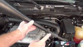
Take a look at picture 1. It shows the VT 25. Here are the directions for servicing that transmission. The fluid specifications are included in the directions. Also, pictures 1, 2, and 3 correlate with this transmission
__________________________________________________
CVT
Transmission Fluid Replacement
Picture 1
1. Raise and support the vehicle.
2. Place a drain pan under the transmission.
3. Remove the lower tube assembly drain plug.
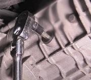
Picture 2
4. Remove the lower tube assembly from the transmission. Allow the fluid to completely drain.
Notice: Refer to Fastener Notice in Cautions and Notices.
5. Install the lower tube assembly into the transmission.
Tighten
Tighten the assembly to 20 N.M (15 lb ft).
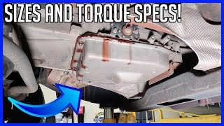
Picture 3
6. Temporarily install the original lower tube plug. Do not tighten.
7. Lower the vehicle.
Important: Do not use ATF P/N 21005966 or P/N 21019223. These fluids are not compatible with this transmission.
8. Fill the transmission to the proper level with Saturn DEX-CVT(R) Fluid P/N 22688912.
9. Install a scan tool.
10. With the vehicle on a flat and level surface, start the vehicle.
11. Circulate the fluid through the transmission using the following procedure:
11.1. With the brake applied, shift the transmission from the PARK (P) to REVERSE (R) for 10 seconds.
11.2. Shift the transmission to DRIVE (D) for 10 seconds.
11.3. Shift the transmission to PARK (P), allowing the engine to remain running.
12. Raise and support the vehicle.
13. Remove the lower tube assembly drain plug and discard.
14. Perform the following procedure to assure proper fluid level:
- If the fluid drains down at a steady stream from the opening, allow the fluid to drain until it stops.
- If no fluid or a very small amount of fluid drains, add fluid to the transmission until a steady stream starts to drain. Stop adding fluid immediately. Allow the fluid to drain until it stops,
15. Install a new lower tube assembly plug and clean any excess fluid from the transmission.
Tighten
Tighten the plug to 11 N.M (97 lb in).
16. Lower the vehicle.
Important: Do not remove the lower tube assembly drain plug.
17. With the scan tool, record the TRANS FLUID TEMP.
- If the TRANS FLUID TEMP is 20°C (68°F) or less, add 0.47 liter (0.5 qt) of fluid to the transmission.
- If the TRANS FLUID TEMP is 40°C (104°F), add 0.71 liter (0.75 qt) of fluid to the transmission.
- If the TRANS FLUID TEMP is 60°C (140°F), add 0.95 liter (1.0 qt) of fluid to the transmission.
- If the TRANS FLUID TEMP is 80°C (176°F), add 1.2 liter (1.25 qt) of fluid to the transmission.
18. Turn OFF the ignition.
19. Add Saturn DEX-CVT additive P/N 22697447 to the transmission using the provided applicator. Inject the entire contents into the transmission.
_______________________________________________
Here are the directions for the AF33-5 transmission. Look at picture 4. It shows the drain on the horizontal axis. Picture 4, 5, and 6 correlate with this transmission and these directions.
Picture 4
Removal Procedure
Caution: Ensure that the vehicle is properly supported and squarely positioned. To help avoid personal injury when a vehicle is on a hoist, provide additional support for the vehicle on the opposite end from which the components are being removed.
Picture 4
1. Raise and support the vehicle.
2. Remove the drain plug and drain fluid. Allow at least 5 minutes for the fluid to drain completely.
3. Remove the gasket from the drain plug and discard.
Installation Procedure
1. Install the new gasket on the drain plug.
Notice: Use the correct fastener in the correct location. Replacement fasteners must be the correct part number for that application. Fasteners requiring replacement or fasteners requiring the use of thread locking compound or sealant are identified in the service procedure. Do not use paints, lubricants, or corrosion inhibitors on fasteners or fastener joint surfaces unless specified. These coatings affect fastener torque and joint clamping force and may damage the fastener. Use the correct tightening sequence and specifications when installing fasteners in order to avoid damage to parts and systems.
2. Install the drain plug.
Tighten
Tighten the drain plug to 40 Nm (30 lb ft).
4. Lower the vehicle.
Notice: Saturn automatic transaxle fluid (ATF), P/N 21005966 and P/N 21019223, is not compatible with this transaxle. If Saturn ATF is used, transaxle damage will result. This transaxle uses Saturn T-IV fluid P/N 22689186. Notice: Do not remove the 3rd gear anchor band bolt located on top of the transmission for checking fluid or adding fluid. Removing the bolt will dislocate internal components and require the transmission to be removed from the vehicle and disassembled for repair.
5. Add approximately 4.06 L (4.29 qt) of Saturn T-IV fluid to unit, using the level gauge location.
6. Make sure vehicle is on level ground.
Important: If the check is necessary at a low oil temperature of 30-40°C (86-104°F), perform check using the COLD range on the level gauge. However, the fluid must be re-checked at the proper fluid temperature.
7. Start engine and operate vehicle until transaxle fluid temperature reaches 60-70°C (140-158°F).
8. Apply parking brake.
9. Depress brake pedal and move shift lever slowly through all gear ranges from park (P) to low (L), pausing for about three seconds in each range. Return shift lever to park (P) range at idle condition.
Picture 5
10. Push retaining clip back and pull level gauge out, wipe off fluid with a clean cloth and reinsert.
Picture 6
11. Pull level gauge out again and check if fluid level is within the HOT range.
12. If fluid is not within the correct level, adjust accordingly:
12.1 If fluid is below the HOT range, add enough to bring it up to the correct level.
12.2 If fluid is above HOT range, drain excess fluid.
________________________
I hope this helps. It's the easiest way I could think to explain it.
Take care and let me know if you have other questions.
Joe
Images (Click to make bigger)
SPONSORED LINKS
Tuesday, March 5th, 2019 AT 7:49 PM