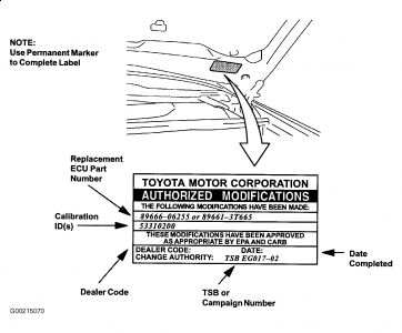
You did say the ECM was reflashed with the new software, and this label was applied under the hood on the driver's side? Toyota suggests test the fuel control circuit for "surging" problems.
ï¬ On Avalon, Camry 2.2L 4-cylinder gasoline models, Camry 3.0L V6, Camry Solara, Celica, Corolla, ECHO, Highlander, MR2, Prius, RAV4, Sienna, Tacoma, Tundra 3.4L V6 and 4Runner, check fuel pump control circuit. See FUEL PUMP CONTROL CIRCUIT under COMPUTERIZED ENGINE CONTROLS in appropriate SYSTEM & COMPONENT TESTING article.
EGR Position Sensor (Camry & Camry Solara) 1. Disconnect electrical connector at EGR position sensor. EGR position sensor is located on top of EGR valve. See Fig. 172 . 2. Using ohmmeter, check resistance between terminals E2 and VC on EGR position sensor. See Fig. 172 . Resistance should be 1500-4300 ohms. If resistance is within specification, reinstall electrical connector on EGR position sensor and go to next step. If resistance is not within specification, replace EGR position sensor. See EGR POSITION SENSOR under ENGINE SENSORS & SWITCHES in REMOVAL, OVERHAUL & INSTALLATION - V6 & V8 article. 3. To test EGR position sensor output voltage, disconnect vacuum hose from EGR valve. Remove glove box for access to Engine Control Module (ECM). Turn ignition on. Using voltmeter, check voltage between ECM terminals E2 (Brown wire) and VC (Yellow wire). See Fig. 173 and Fig. 174 . Voltage should be 4.5-5.5 volts. Remove voltmeter. 4. Connect voltmeter between ECM terminals E2 (Brown wire) and EGLS (White/Green wire). See Fig. 175 and Fig. 176 . Using vacuum pump, apply 5.1 in. Hg of vacuum to EGR valve and note voltage. Voltage should be 3.2-5.1 volts with vacuum applied on EGR valve. Release vacuum from EGR valve and note voltage. Voltage should be .4-1.6 volts with vacuum released from EGR valve. Replace EGR position sensor if voltage is not within specification. See EGR POSITION SENSOR under ENGINE SENSORS & SWITCHES in REMOVAL, OVERHAUL & INSTALLATION - V6 & V8 article. Remove vacuum pump and reinstall vacuum hose on EGR valve. NOTE: EGR position sensor may also be referred to as EGR valve position sensor.
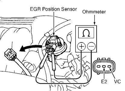
Also you can pull of the vacuum hose and use a vacuum pum with engine running, if it starts to stall or run rough with vacuum applied, release the vacuum, if it smoothes out, the EGR isnt sticking...this has an electronic position sensor mounted on top of it, if it's open at the wrong time, a code will set and turn on the check engine light.
IAC TESTING:
Camry Solara, Tacoma & Tundra 3.4L V6 1. Start engine. Warm engine to normal operating temperature. Ensure idle speed is within specification. See IDLE SPEED & MIXTURE in ON-VEHICLE ADJUSTMENTS - V6 & V8 article. 2. Turn ignition off. Apply parking brake and place transmission/transaxle in Neutral. Ensure A/C is off. 3. On Camry Solara, install Jumper Wire (SST 09843-18020 or SST 09843-18040) between terminals TC and E1 on data link connector No. 1 located at passenger's side of engine compartment, near strut tower. See Fig. 137 . Go to step 5 . 4. On Tacoma and Tundra, note location of data link connector No. 3 at driver's side of instrument panel. See Fig. 30 and Fig. 31 . Install Jumper Wire (SST 09843-18020 or SST 09843-18040) between terminals No. 4 (CG) and 13 (TC) on data link connector No. 3. See Fig. 139 . Go to next step. 5. On all models, start engine and note engine speed. On Camry Solara and Tacoma, engine speed should increase to 1000 RPM for 5 seconds and then return to idle speed. On Tundra, engine speed should increase to 900-1500 RPM for 5 seconds and then return to idle speed. On all models, if engine speed is not as specified, test IAC valve resistance and IAC valve operation. Go to next step. If engine speed is as specified, remove jumper wire. Turn ignition off. 6. To test IAC valve resistance, ensure ignition is off. Disconnect electrical connector at IAC valve. IAC valve is located on lower area of throttle body. Using ohmmeter, checking resistance between +B terminal and each remaining terminal on IAC valve. See Fig. 141 -Fig. 142 . 7. Replace IAC valve if resistance is not within specification. See IAC VALVE RESISTANCE table.
Jun 22, 2009 at 1:13 PM