Let me know if this helps. If you need anything additional, let me know. Also, the attached pictures correlate with the directions.
___________________________________________________
2002 Chevy Truck Avalanche 1500 4WD V8-5.3L VIN T
8.6, 9.5 Inch Axle
Vehicle Transmission and Drivetrain Differential Assembly Service and Repair Procedures Rear Drive Axle Axle Shaft Replacement 8.6, 9.5 Inch Axle
8.6, 9.5 INCH AXLE
Rear Axle Shaft Replacement
Removal Procedure
pic 1
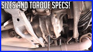
1. Raise the vehicle. Refer to Vehicle Lifting.
2. Remove the tire and wheel assembly.
3. Remove the brake caliper.
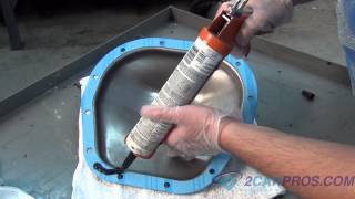
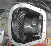
4. Remove the rear cover and the gasket.
5. Remove the pinion shaft locking bolt.
Pic 2
6. On axles without a locking differential, remove the pinion shaft
pic 3
7. On axles with a locking differential, remove the shaft part way. Rotate the case until the pinion shaft touches the housing.
Pic 4
8. On axles with a locking differential, use a screwdriver, or a similar tool, in order to enter the differential case and rotate the lock (1) until the lock aligns with the thrust block (2).
Pic 5
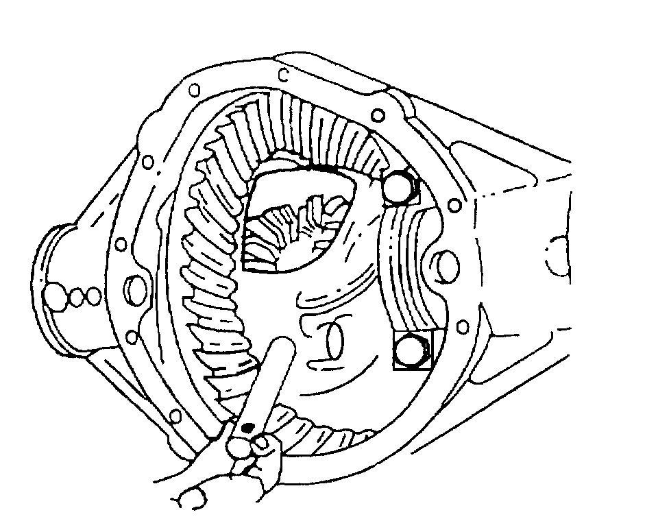
9. Push the flange of the axle shaft (1) toward the differential.
10. Remove the C-lock (4) from the button end of the axle shaft (1).
Important: When removing the axle shaft, do not rotate the shaft. Rotating the shaft will misalign the gears. Misaligning the gears will make the assembly difficult.
11. Remove the axle shaft (1) from the housing (5).
Installation Procedure
pic 6
Important: Carefully insert the axle shaft in order to not damage the seal.
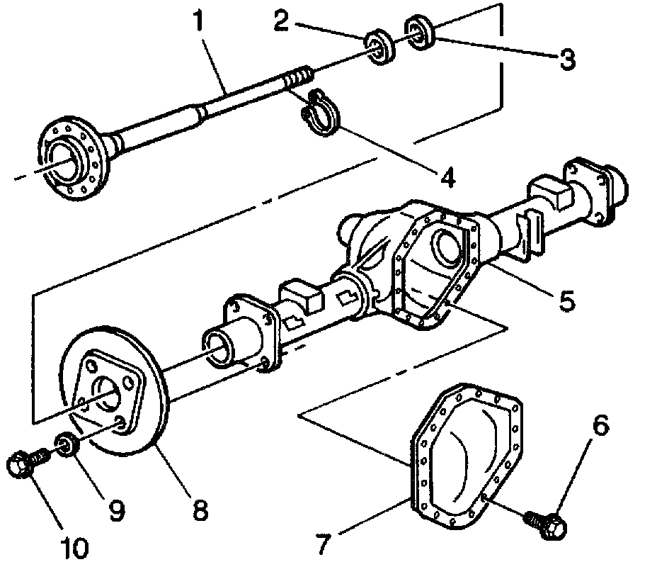
1. Install the axle shaft (1) into the rear axle housing (5).
2. Slide the axle shaft (1) into place allowing the splines to engage the differential side gear.
3. On axles without a locking differential, place the lock (4) on the button end of the axle shaft (1).
4. On axles with a locking differential, keep the pinion shaft partially withdrawn.
Pic 7
5. On axles with a locking differential, place the C-lock (1) on the axle shaft (3) so that the ends are flush with the thrust block (2).
6. Pull the shaft flange outward in order to seat the lock in the differential gear.
Pic 8
7. Align the hole in the pinion shaft with the bolt hole in the differential case.
Notice: Refer to Fastener Notice in Service Precautions.
8. Install the new pinion shaft locking bolt.
Tighten the pinion shaft locking bolt to 34 Nm (25 lb ft).
9. Install the rear cover and the gasket.
10. Install the brake caliper.
11. Install the tire and wheel assembly.
12. Fill the rear axle. Use the proper fluid.
13. Lower the vehicle.
_________________________________________
Adjustment:
8.6 Inch Axle
Vehicle Transmission and Drivetrain Differential Assembly Service and Repair Procedures Rear Drive Axle - Locking/Limited Slip Rear Axle Locking Differential Adjustment 8.6 Inch Axle
8.6 INCH AXLE
Locking Differential Adjustment (8.6 Inch Axle)
Tools Required
- J 7872 Magnetic Base Dial Indicator
- J 8001-3 Dial Indicator
Adjustment of the Differential
Important: If it is necessary to replace the left side gear (cam unit) and disc assembly, the right side gear and disc assembly, or the thrust block, the entire differential must be adjusted. The differential is adjusted using selective thickness thrust washers between the clutch pack assemblies and the case and/or different selective thickness thrust blocks.
When adjusting the differential, note the following:
Build up the clutch disc packs properly.
Proper clearance between parts is critical to the operation of the unit.
Adjust the backlash and thrust block clearance in the following order:
1. The left side gear backlash
2. The right side gear backlash
3. The thrust block clearance
Left Side Gear Backlash Adjustment
pic 9
1. Install the new left side thrust washer into the flange end of the differential case.
Pic 10
2. Install the left side gear (cam unit) and clutch pack assembly into the differential case.
3. Install the pinion gears with the pinion thrust washers into the differential case.
Align the openings of the pinion gears and the pinion thrust washer to the pinion shaft opening in the differential case.
4. Install the pinion shaft. It may be necessary to press down on the side gear in order to align the pinion gear shaft opening with the pinion shaft opening in the differential case.
If the pinion shaft cannot be installed after pressing on the side gear, replace the side gear thrust washer with a thinner washer.
Notice: Refer to Fastener Notice in Service Precautions.
5. Install the pinion shaft lock bolt.
Tighten the pinion shaft lock bolt finger tight.
6. Rotate the pinion gear closest to the lock bolt so that one of the teeth is pointing downward (perpendicular to the ring gear flange).
7. Install a brass drift between the side gear and the pinion shaft.
Press the brass drift in far enough in order to compress the clutch discs.
Pic 11
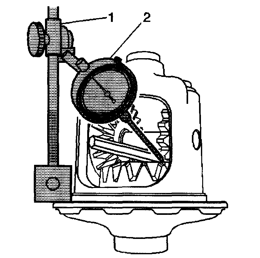
8. Measure the backlash of the pinion gear and the side gear by doing the following:
8.1. Install the J 7872 (1) to the ring gear flange.
8.2. Loosely clamp the J 8001-3 (2) onto the stem on the J 7872 (1).
8.3. Place the contact pad of the J 8001-3 on one of the teeth of the pinion gear closest to the pinion shaft lock bolt. Turn the dial of the J 8001-3 until the needle and the dial face indicate zero.
8.4. Tighten the lock nut of the J 8001-3 finger tight.
8.5. Pull the pinion gear firmly into the differential case seat.
8.6. Rotate the pinion gear back and forth.
8.7. Measure the backlash.
The backlash for the pinion gears should be 0.000 - 0.076 mm (0.000 - 0.003 inch).
9. If the backlash is too large, install a thicker side gear thrust washer and recheck the backlash.
10. If the backlash is too small, install a thinner side gear thrust washer and recheck the backlash.
Left side gear thrust washers are available in the following sizes:
Washer Sizes
0.559 mm (0.022 inch)
0.686 mm (0.027 inch)
0.813 mm (0.032 inch)
0.914 mm (0.036 inch)
1.016 mm (0.040 inch)
1.118 mm (0.044 inch)
1.219 mm (0.048 inch)
1.321 mm (0.052 inch)
Right Side Gear Backlash Adjustment
1. If necessary, remove the following from the differential case:
1.1. The pinion lock shaft bolt
1.2. The pinion shaft
1.3. The pinion gears
1.4. The pinion gear thrust washers
1.5. The left side gear (cam unit) and clutch disc assembly
2. Install the right side gear thrust washer into the bell-end of the differential case.
3. Install the right side gear and clutch pack assembly into the differential case.
4. Install the pinion gears with the pinion thrust washers into the differential case.
Align the openings of the pinion gears and the pinion thrust washer to the pinion shaft opening in the differential case.
5. Press down on the side gear and install the pinion shaft.
If the side gear cannot be pressed down far enough to install the pinion shaft, replace the side gear shim with a thinner shire.
Notice: Refer to Fastener Notice in Service Precautions.
6. Install the pinion shaft lock bolt.
Tighten the pinion shaft lock bolt finger tight.
7. Rotate the pinion gear so that one of the teeth is pointing downward (perpendicular to the ring gear flange).
Pic 12
8. Install a brass drift between the side gear and the pinion shaft.
Press the brass drift in enough in order to compress the clutch discs.
Pic 13
9. Measure the backlash of the pinion gear and the right side gear by doing the following:
9.1. Install the J 7872 (1) to the ring gear flange.
9.2. Loosely clamp the J 8001-3 (2) onto the stem on the J 7872 (1).
9.3. Place the contact pad of the J 8001-3 on one of the teeth of the pinion gear closest to the pinion shaft lock bolt.
Turn the dial of the J 8001-3 until the needle and the dial face indicate zero.
9.4. Tighten the lock nut of the J 8001-3 finger tight.
9.5. Pull the pinion gear firmly into the differential case seat.
9.6. Rotate the pinion gear back and forth.
9.7. Measure the backlash.
The backlash for the pinion gears should be 0.000 - 0.076 mm (0.000 - 0.003 inch).
10. If the backlash is too large, install a thicker side gear shim and recheck the backlash.
11. If the backlash is too small, install a thinner side gear shim and recheck the backlash again.
Right side gear shims are available in the following sizes:
Shim Sizes
0.254 mm (0.010 inch)
0.381 mm (0.015 inch)
0.508 mm (0.020 inch)
0.635 mm (0.025 inch)
0.762 mm (0.030 inch)
0.889 mm (0.035 inch)
1.016 mm (0.040 inch)
1.143 mm (0.045 inch)
Thrust Block Clearance Adjustment
pic 14
Important: The left and right side gear backlash measurements must be done before the thrust block measurement can be completed.
1. Install the left side gear thrust washer into the differential case.
Pic 15
2. Install the left side gear (cam unit) and clutch disc assembly into the differential case.
3. Install the right side shim into the differential case.
4. Install the right side gear and clutch disc assembly into the differential case.
5. Install the pinion shaft.
6. Install the pinion shaft bolt.
Tighten the pinion shaft bolt finger tight.
Pic 16
7. Install a brass drift between the left side gear and the pinion shaft. Press the brass drift in far enough in order to compress the clutch disc assembly and hold the left side gear assembly in place.
8. Install a brass drift between the right side gear and the pinion shaft.
Press the brass drift in far enough in order to hold the right side gear assembly in place.
Pic 17
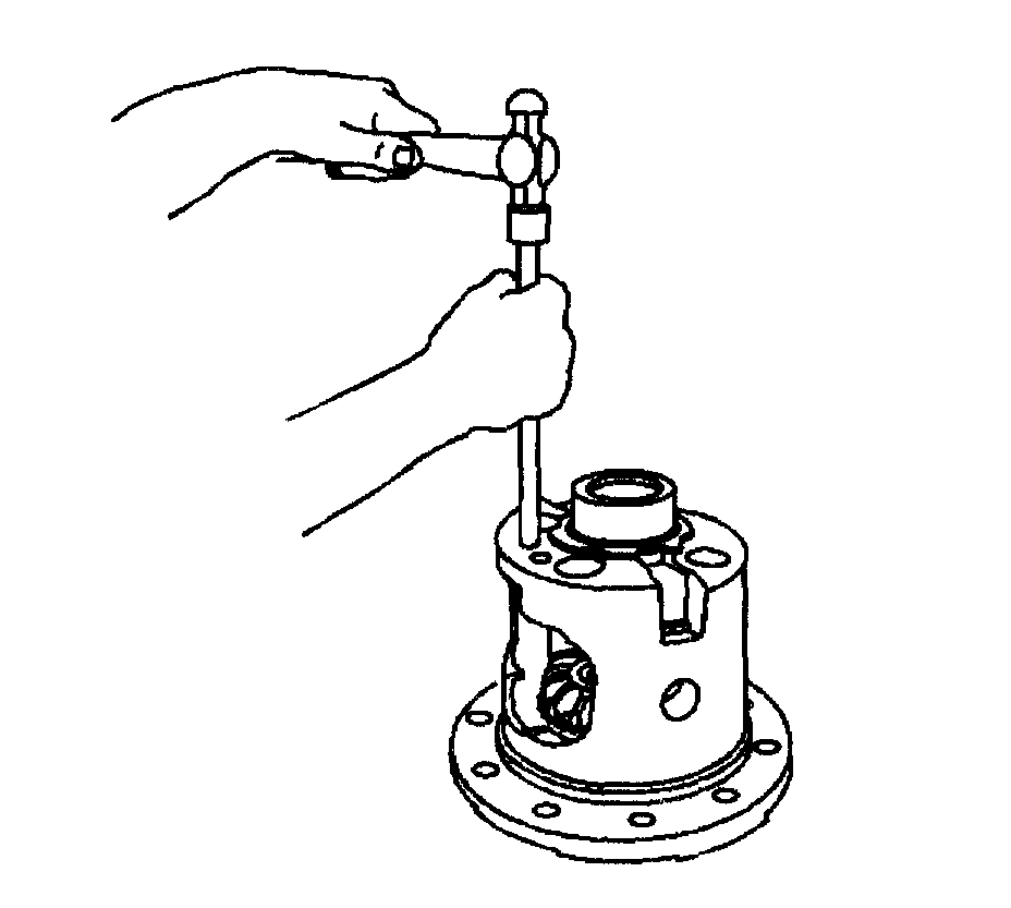
Important: Do not measure the distance between the side gear teeth.
9. Measure the distance between the side gear faces using a 25.4-50.8 mm (1-2 inch) telescoping gage.
10. Remove the telescoping gage.
11. Measure the telescoping gage with a micrometer.
Record the measurement.
12. Compare the measurement obtained in Step 11 to the thrust block sizes available. If the measurement is equal to one of the thrust blocks sizes available, then select that thrust block.
13. If the measurement obtained in Step 11 is not equal to one of the thrust blocks sizes available, then select the thrust block that is smaller than the measurement.
For example, if the measurement is 33.93 mm (1.336 inch), select the 33.78 mm (1.330 inch) thrust block.
Important: The backlash must be rechecked and adjusted to specification anytime the left and/or the right thrust washers are replaced.
14. If the measurement obtained in Step 11 is less than 33.83 mm (1.322 inch), then reduce the left side gear thrust washer or the right side gear shim thickness in order to increase the thrust block opening.
15. If the measurement obtained in Step 11 is greater than 34.19 mm (1.346 inch), then increase the left side gear thrust washer or the right side gear shim thickness in order to decrease the thrust block opening.
16. Recheck the left and/or right side gear backlash and adjust as necessary.
17. Recheck the thrust block clearance and adjust as necessary.
________________________________
Locking Differential Assembly:
rear differential
111
Community 23 Create Quote
2002 Chevy Truck Avalanche 1500 4WD V8-5.3L VIN T
8.6, 9.5 Inch Axle
Vehicle Transmission and Drivetrain Differential Assembly Service and Repair Procedures Rear Drive Axle - Locking/Limited Slip Rear Axle Locking Differential Assemble 8.6, 9.5 Inch Axle
8.6, 9.5 INCH AXLE
Locking Differential Assemble (8.6, 9.5 Inch Axles)
pic 18
Important: The left and right side gear backlash and thrust block thickness measurement must be completed before the components of the locking differential can be assembled.
1. Install the left side gear thrust washer.
Pic 19
2. Install the left side gear cam unit and clutch disc assembly.
3. Install the right side gear thrust washer.
4. Install the right side clutch pack assembly.
5. Install the right side gear.
Important: If the original pinion gears and thrust washers are being re-used, install the pinion gears and thrust washers on the same side as when removed.
6. Install the pinion gear and the pinion thrust washers.
Place the pinion gears and the pinion thrust washers 180 degrees apart.
7. Rotate the pinion gears and the pinion thrust washers 90 degrees and align the pinion gears with the pinion shaft opening in the differential case.
8. Install the thrust block.
The open side of the thrust block must face the window opening.
9. Install the pinion shaft.
10. Install the new pinion shaft lock bolt.
Tighten the pinion shaft lock bolt finger tight.
Pic 20
11. Install the governor assembly.
12. Install the governor bushing using a hammer and a brass drift.
Press the bushing into place until there is 0.025 - 0.076 mm (0.010 - 0.030 inch) of shaft end play.
Pic 21
13. Install the latching bracket assembly.
The straight end of the latching bracket spring must be over and outside the governor assembly shaft.
14. Install the latching bracket bushing using a hammer and a brass drift.
Press the bushing into place until there is 0.000 0.051 mm (0.000 - 0.002 inch) of shaft end play.
15. Tighten the pinion shaft lock bolt.
Tighten the pinion shaft lock bolt to 36 Nm (27 lb ft).
16. Install the ring gear, if necessary.
________________________________________________________
Let me know if this helps.
Take care,
Joe
Images (Click to make bigger)
SPONSORED LINKS
Tuesday, December 31st, 2019 AT 7:59 PM