Hi and thanks for using 2CarPros. Com. There could be a few different issues causing this problem. I am going to start from under the dash and go through the system for you to check/diagnose.
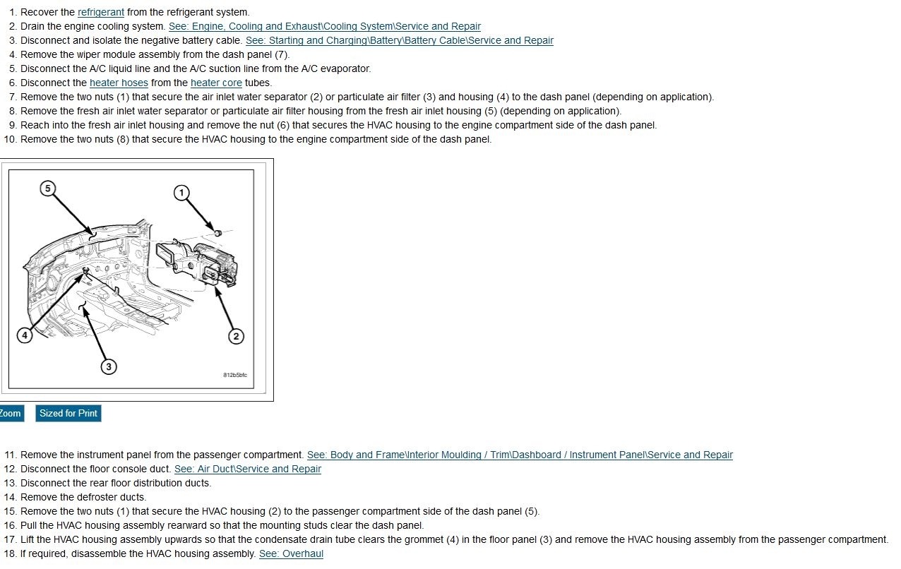
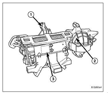
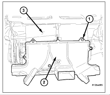
Starting with the HVAC Housing Assembly: (see picture one)
All models are equipped with a common HVAC housing assembly that combines A/C and heating capabilities into a single unit mounted within the passenger compartment. The HVAC housing assembly consists of three separate housings:
HVAC housing - The HVAC housing (1) is mounted to the dash panel behind the instrument panel and contains the A/C evaporator and the blower motor resistor or power model, depending on application. The HVAC housing consists of a upper and a lower housing that are attached together and has mounting provisions for the air inlet housing, blower motor, air distribution housing and the HVAC wire harness.
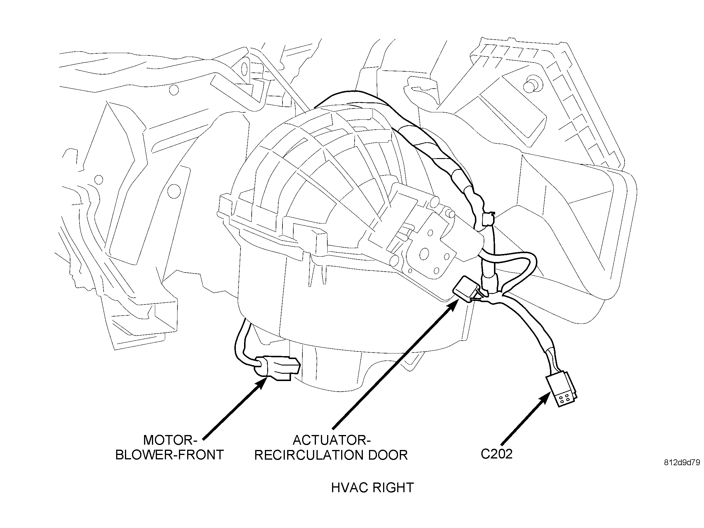
Air inlet housing - The air inlet housing (2) is mounted to the right end of the HVAC housing and contains the recirculation-air door and actuator.
Air distribution housing - The air distribution housing (3) is mounted to the rear of the HVAC housing and contains the heater core, blend-air door(s) and actuator(s), mode-air doors and actuator and door linkage.
The heating-A/C system is a blend-air type system. The blend-air doors control the amount of conditioned air that is allowed to flow through, or around, the heater core. The dual zone heating A/C system uses two blend door actuators while the single zone system uses only one blend door actuator.
The A/C system is designed for the use of a non-CFC, R-134a refrigerant and uses an A/C evaporator to cool and dehumidify the incoming air prior to blending it with the heated air. A temperature control determines the discharge air temperature by operating the blend door actuator(s), which moves the blend-air door(s). This allows an almost immediate control of the output air temperature of the system. The mode door actuator operates the mode-air doors which direct the flow of the conditioned air out the various air outlets, depending on the mode selected. The recirculation door actuator operates the recirculation-air door which closes off the fresh air intake and recirculates the air already inside the vehicle. The electric door actuators are connected to the vehicle electrical system by the HVAC wire harness. The blower motor controls the velocity of air flowing through the HVAC housing assembly by spinning the blower wheel within the HVAC housing at the selected speed by use of the blower motor resistor or power model, depending on application.
The air distribution housing must be removed from the HVAC housing and disassembled for service of the mode-air and blend-air doors. The air inlet housing must be removed from HVAC housing and disassembled for service of the recirculation-air door. The HVAC housing must be removed from the vehicle and disassembled for service of the A/C evaporator.
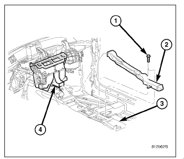
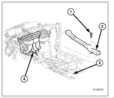
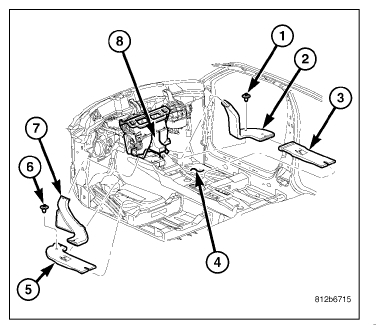
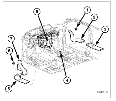
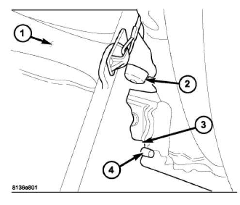
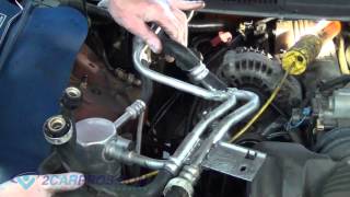
Pictures 2, 3, 4, 5, and 6 are of the duct work to the rear of the vehicle.
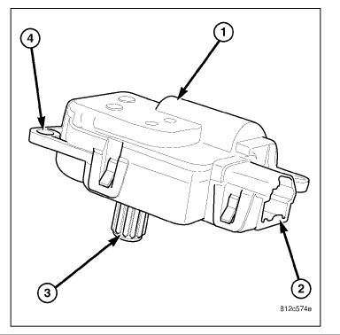
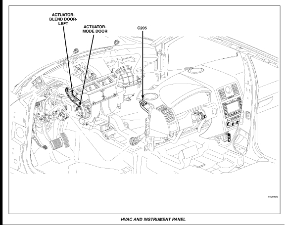
If everything is properly attached, then I would suggest checking the HVAC mode door actuator. Picture 7 and 8 are of the mode actuator. See attached description:
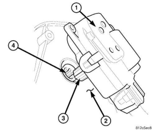
The mode door actuator (1) is a reversible, 12-volt direct current (DC), servo motor. The mode door actuator is located on the driver side end of the HVAC air distribution housing, close to the instrument panel. The mode door actuator is mechanically connected to the floor, defrost/demist and the panel-air doors.
The mode door actuator is interchangeable with the actuators for the blend-air door(s) and the recirculation-air door. Each actuator is contained within an identical black molded plastic housing with an integral wire connector receptacle (2). Each actuator also has an identical output shaft with splines (3) that connects it to its door linkage and three integral mounting tabs (4) that allow the actuator to be secured to the HVAC housing. The mode door actuator does not require mechanical indexing to the mode-air doors, as it is electronically calibrated by the A/C-heater control.
The mode door actuator is connected to the A/C-heater control through the vehicle electrical system by a dedicated two-wire lead and connector of the HVAC wire harness. The mode door actuator can move the floor, defrost/demist and the panel-air doors in two directions. When the A/C-heater control pulls the voltage on one side of the motor connection high and the other connection low, the mode-air doors will move in one direction. When the A/C-heater control reverses the polarity of the voltage to the motor, the mode-air doors moves in the opposite direction.
When the A/C-heater control makes the voltage to both connections high or both connections low, the mode-air doors stop and will not move. The A/C-heater control uses a pulse-count positioning system to monitor the operation and relative position of the mode door actuator and the mode-air doors. The A/C-heater control learns the mode-air doors stop position during the calibration procedure and will store a diagnostic trouble code (DTC) for any problems it detects in the mode door actuator circuits.
The mode door actuator is diagnosed using a scan tool.
Finally, the blend air door actuator. It determines air temperature. See description:
The blend door actuators (1) are reversible, 12 volt direct current (DC), servo motors. Models equipped with the MTC single zone heating-A/C system have a single blend-air door, which is controlled by a single blend door actuator. Models with the ATC dual zone heating-A/C system have two blend-air doors, which are controlled by two blend door actuators.
The blend door actuator for the single zone heating-A/C system is located on the driver side end of the HVAC air distribution housing, close to the dash panel.
For the dual zone heating-A/C system, the same blend door actuator used for the single zone system becomes the driver side blend door actuator, which is mechanically connected to only the driver side blend-air door. A second separate blend door actuator is also located on the passenger side of the HVAC air distribution housing which is mechanically connected to only the passenger side blend-air door.
The blend door actuators are interchangeable with each other, as well as with the actuators for the mode-air door and the recirculation-air door. Each actuator is contained within an identical black molded plastic housing with an integral wire connector receptacle (2). Each actuator also has an identical output shaft with splines (3) that connects it to its respective door linkage and three integral mounting tabs (4) that allow the actuator to be secured to the HVAC housing. The blend door actuators do not require mechanical indexing to the blend-air doors, as they are electronically calibrated by the A/C-heater control.
The blend door actuators are connected to the A/C-heater control through the vehicle electrical system by a dedicated two-wire lead and connector of the HVAC wire harness. The blend door actuator(s) can move the blend-air door(s) in two directions. When the A/C-heater control pulls the voltage on one side of the motor connection high and the other connection low, the blend-air door will move in one direction. When the A/C-heater control reverses the polarity of the voltage to the motor, the blend-air door moves in the opposite direction.
When the A/C-heater control makes the voltage to both connections high or both connections low, the blend-air door(s) stops and will not move.
On ATC equipped vehicles, the A/C-heater control uses a pulse-count positioning system to monitor the operation and relative position of the blend door actuators and the blend-air doors. The A/C-heater control learns the blend-air doors stop positions during the calibration procedure and will store a diagnostic trouble code (DTC) for any problems it detects in the blend door actuator circuits.
On MTC equipped vehicles, the A/C-heater control uses a timer-type calibration procedure to check relative position of the blend door actuator and the blend-air door. The A/C-heater control learns the blend-air door stop positions during the calibration procedure and will store a diagnostic trouble code (DTC) for any problems it detects in the
blend door actuator circuits.
The blend door actuator(s) are diagnosed using a scan tool.
Now, since the blend air doors are providing AC to the front, that leads me to believe the problem is related to the mode door actuator mentioned prior. The easiest way to check it is with a scan tool, but it must be a scan tool which can read codes other than engine related and it must see real time data.
I hope this helps. There is a lot of information, but I wanted to provide everything.
If you have additional questions, let me know.
Take care,
Joe
Images (Click to make bigger)
Friday, May 18th, 2018 AT 9:35 PM