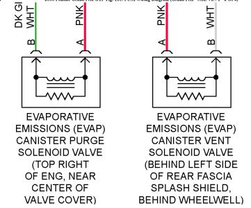
Vent solenoid valve is located on the rear left frame rail near the left rear suspension for VIN 1 supercharged. Not located on the engine like described in the wiring diagram.
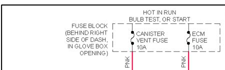
DTC P0449: EVAP CANISTER VENT SOLENOID VALVE CONTROL CIRCUIT Circuit Description Ignition voltage is supplied directly to EVAP vent valve solenoid. PCM controls solenoid by grounding control circuit through an internal switch called a driver. Primary function of driver is to supply ground for component being controlled. Each driver has a fault line which is monitored by PCM. When PCM is commanding a component on, voltage of control circuit should be low (near zero volts). When PCM is commanding control circuit to a component off, voltage potential of circuit should be high (near battery voltage). If fault detection circuit senses a voltage other than what is expected, fault line status will change, causing DTC to set. DTC will set when PCM detects that the commanded state of the driver and actual state of the control circuit do not match and condition is present for a minimum of 30 seconds.
NOTE: For circuit reference, see WIRING DIAGRAMS article.
Page 1 of 2 SELF-DIAGNOSTICS - 3.8L -2000 Pontiac Grand Prix GTP1. Perform On-Board Diagnostic (OBD) system check. See ON-BOARD DIAGNOSTIC (OBD) SYSTEM CHECK under SELF-DIAGNOSTIC SYSTEM. After performing OBD system check, go to next step. 2. Turn ignition on, with engine off. Using scan tool, command vent solenoid on and off. If solenoid responds as commanded, see DIAGNOSTIC AIDS . If solenoid does not respond as commanded, go to next step. 3. Turn ignition off. Disconnect vent solenoid. Turn ignition on, with engine off. Using a test light connected to ground, probe vent solenoid ignition feed circuit. If test light illuminates, go to next step. If test light does not illuminate, go to step 10 . 4. Connect test light between vent solenoid ignition feed and ground circuits. Using scan tool, command vent solenoid on and off. If test light turns on and off, go to step 8 . If test light does not turn on and off, go to next step. 5. If test light remains illuminated, go to step 7 . If test light remains off, go to next step. 6. Check vent solenoid control circuit for an open or short to voltage. Repair as necessary. After repairs, go to step 13 . If circuit is okay, go to step 9 . 7. Check vent solenoid control circuit for a short to ground. Repair as necessary. After repairs, go to step 13 . If circuit is okay, go to step 9 . 8. Check for faulty vent solenoid connections. Repair as necessary. After repairs, go to step 13 . If connections are okay, go to step 11 . 9. Check for faulty PCM connections. Repair as necessary. After repairs, go to step 13 . Ifconnections are okay, go to step 12 . 10. Repair vent solenoid ignition feed circuit. After repairs, go to step 13 . 11. Replace vent solenoid. After replacing solenoid, go to step 13 . 12. Replace PCM. Program replacement PCM using required equipment. After replacing PCM, go to next step. 13. Using scan tool, clear DTCs. Operate vehicle under conditions required to set DTC. Check for DTCs. If this DTC is set, go to step 2 . If DTC is not set, system is okay. Diagnostic Aids Using FREEZE FRAME and/or FAILURE RECORDS data mode may aid in locating an intermittent condition. If DTC cannot be duplicated, information included in FREEZE FRAME and/or FAILURE RECORDS data can be useful in determining how many miles since DTC set. FAIL COUNTER and PASS COUNTER can also be used to determine how many ignition cycles diagnostic reported a pass or a fail condition. To isolate when DTC failed, operate vehicle within same freeze frame conditions (RPM, load, vehicle speed, temperature, etc.). Hope this helps! Any more questions and please ask in the forum, if you are having trouble, and dont tell me, I dont continue!
SPONSORED LINKS
Friday, March 13th, 2009 AT 12:12 PM


