Basic tests still Apply in every case
check for fuel pressure ,spark ,vacuum leaks ,EGR operation and compression
check fuses and relay
as for codes each code point to a troubled area and translate to a list of checking and testing
this is a quick page for trouble codes table
https://www.2carpros.com/kpages/diagnostic_trouble_codes.htm
p1899
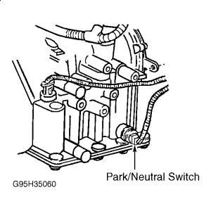
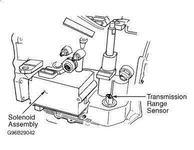
Park/neutral switch is used on 3-speed models and transmission range sensor is used on 4-speed models. Transmission range sensor may be referred to as park/neutral switch.
Apply parking brake. Using scan tool, read park/neutral switch state while moving shift lever from Park to Reverse.
If scan tool displays P/N and D/R, go to next step. If scan tool does not display P/N and D/R, go to step 6).
Conditions required to set DTC are not present at this time. The DTC may be stored in Powertrain Control Module (PCM) when PCM detects incorrect park/neutral switch state for a given mode of vehicle operation. Possible causes are: defective connector terminals or wiring, defective park/neutral switch, transaxle internal problem or defective PCM.
Check for defective wiring or connections at PCM and park/neutral switch (3-speed) or transmission range sensor (4-speed) located on side of transaxle.
The PCM is located between driver's side front fender and power distribution center, near battery.
If defective wiring or connections exist, repair as necessary.
. If no defective wiring or connections exist, see INACTIVE TROUBLE CODE CONDITION.
Ensure ignition is off. Place shift lever in Park. Disconnect connectors from Powertrain Control Module (PCM). The PCM is located between driver's side front fender and power distribution center, near battery.
Using ohmmeter, check resistance between ground and PCM connector terminal No. 76 (Black/White wire) while moving shift lever from Park to Reverse.
If resistance changes from less than 5 ohms to more than 5 ohms, replace PCM. Perform TEST VER-2A. If resistance does not change from less than 5 ohms to more than 5 ohms, go to next step.
If resistance does not remain less than 5 ohms at all times, go to next step. If resistance remains less than 5 ohms at all times, repair short to ground in Black/White wire between PCM and park/neutral switch (3-speed) or transmission range sensor (4-speed). Perform TEST VER-2A. Park/neutral switch (3-seed) or transmission range sensor (4-speed) are located on transaxle.
Disconnect connector at park/neutral switch (3-seed) or transmission range sensor (4-speed) on transaxle.
Using ohmmeter, check resistance between Black/White wire on connector for park/neutral switch (3-speed) or transmission range sensor (4-speed) and PCM connector terminal No. 76 (Black/White wire). If resistance is less than 5 ohms, replace park/neutral switch (3-speed) or transmission range sensor (4-speed). Perform TEST VER-2A. If resistance is 5 ohms or more, repair open circuit in Black/White wire between PCM and park/neutral switch (3-speed) or transmission range sensor (4-speed).
P0132
TEST TC-62A - UPSTREAM O2 SENSOR SHORTED TO
Turn ignition on. Using scan tool, read upstream oxygen sensor voltage.
If upstream oxygen sensor voltage is more than 1.2 volts, go to next step.
If upstream oxygen sensor voltage is not more than 1.2 volts, go to step 5).
Turn ignition off. Disconnect connector at upstream oxygen sensor, mounted on exhaust manifold.
Inspect connector for pushed out, miswired or damaged terminals.
If terminals are pushed out, miswired or damaged, repair connector as necessary. Perform TEST VER-5A. If terminals are not pushed out, miswired or damaged, go to next step.
Turn ignition on. Using scan tool, read upstream oxygen sensor voltage with connector for upstream oxygen sensor disconnected.
If upstream oxygen sensor voltage is more than 1.2 volts, repair short to voltage in Black/Dark Green wire between PCM and upstream oxygen sensor.
Perform TEST VER-5A.
The PCM is located between driver's side front fender and power distribution center, near battery. If upstream oxygen sensor voltage is not more than 1.2 volts, replace upstream oxygen sensor.
Perform TEST VER-5A.
Wiggle wiring harness and connector at upstream oxygen sensor, mounted on exhaust manifold, while monitoring upstream oxygen sensor voltage.
If upstream oxygen sensor voltage increases to more than 1.2 volts at any time while moving wiring harness, repair wiring harness or connector for short to voltage as necessary. Perform TEST VER-5A.
If upstream oxygen sensor voltage does not increase to more than 1.2 volts at any time while moving wiring harness, go to next step.
Conditions required to set DTC are not present at this time. DTC may be stored in Powertrain Control Module (PCM) if upstream oxygen sensor voltage is more than 1.2 volts. Possible causes are: upstream oxygen sensor signal wire shorted to another circuit, dirt/moisture or grease causing voltage tracking in connector, defective upstream oxygen sensor, defective PCM, defective connector terminals or wiring. Go to next step.
Check for defective wiring or connections at upstream oxygen sensor and PCM. The PCM is located between driver's side front fender and power distribution center, near battery. If defective wiring or connections exist, repair as necessary. Perform TEST VER-5A. If no defective wiring or connections exist, go to next step.
Turn ignition off. Disconnect connector at upstream oxygen sensor. Inspect connector for pushed out, miswired or damaged terminals. If terminals are pushed out, miswired or damaged, repair connector as necessary. Perform TEST VER-5A. If terminals are not pushed out, miswired or damaged
P0172
TEST TC-118A - FUEL SYSTEM RICH
Using scan tool, check for stored Diagnostic Trouble Codes (DTCs). If no stored DTCs exist pertaining to any oxygen sensors, go to next step. If any stored DTCs exist pertaining to any oxygen sensors, perform test procedures for that DTC before proceeding.
This DTC may be stored in Powertrain Control Module (PCM) when PCM determines fuel system is running too rich for at least 2 trips. If this condition exists, Malfunction Indicator Light (MIL) in message center will illuminate and remain on, but goes off if conditions required to set DTC are not found on the following trips.
Possible causes are: defective wiring or connectors, defective catalytic converter, defective EGR valve, defective fuel pump, defective injectors, defective fuel pressure regulator, defective MAP sensor, defective upstream oxygen sensor, defective PCM or engine mechanical problems. Go to next step.
Perform oxygen sensor heater test.
. If oxygen sensor heater passes the test, go to next step.
Turn ignition on with engine off. Using using scan tool, read the long term adaptive memory values. If long term adaptive memory is -20 percent to -38 percent, perform TEST TC-118B. If long term adaptive memory is not -20 percent to -38 percent, condition required to set DTC is not present. Test is complete. Perform TEST VER-5A.
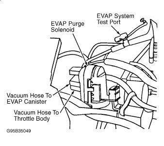
P0443
Oct 5, 2009 at 6:14 AM