Not charging

Tiny
GLEAN SPANN
  • MEMBER
  • 1988 CADILLAC BROUGHAM
  • 5.0L
  • V8
  • 2WD
  • AUTOMATIC
  • 110,000 MILES
Car was not charging so purchased new alternator, still not charging. Tested alternator and it tested good. Disconnected alternator from car electrical system and ran it to another battery on cart exit to car system will charge battery on cart it when connected to car wiring harness it will not charge. With meter on battery the voltage steadily goes down just as if there is no alternator. Do you think there is a short to ground and if so how do I test for it?
Saturday, January 2nd, 2021 AT 6:09 PM

9 Replies

Tiny
CARADIODOC
  • MECHANIC
  • 33,752 POSTS
Shorts to ground blow fuses or burn fuse link wires open.

1988 was the second year for this redesigned generator, and it was real common to have four to six repeat failures. Due to their design, they develop huge voltage spikes that can destroy the internal diodes and voltage regulator, and interfere with computer sensor signals. The battery is the key component in damping and absorbing those spikes. As they age and the lead flakes off the plates, they lose their ability to do that. To reduce the number of repeat failures, always replace the battery at the same time, unless it's less than about two years old. The old battery will work fine in an '86 or older model.

The first thing to look for is whether the "Charge" or "Battery" warning light turns on when you turn the ignition switch to "run". If it does not, check the "AC" fuse in the inside fuse box. That circuit is the "turn-on" signal for the voltage regulator.

Next, go to the wires on the back of the generator. The fat wire bolted to the output stud must have full battery voltage all the time. Next, check for battery voltage, (12 volts), on the smaller red wire in the small plug. That's the one with my red arrow in the second diagram. To be most accurate, these readings should be taken with the plug still plugged in. Back-probe through the back of the connector.

If those voltages are okay, check the voltage on the brown wire. Expect to find close to 2.0 volts with the ignition switch in the "run" position, then it will jump up to full charging voltage of 13.75 to 14.75 volts when the engine is running, if the charging system is working.
Was this
answer
helpful?
Yes
No
+1
Saturday, January 2nd, 2021 AT 7:25 PM
Tiny
GLEAN SPANN
  • MEMBER
  • 7 POSTS
Thanks for reply and schematic. I am going to ship now and rethink this. Car was attempted stolen and column busted wire ran to starter and a hot to coil. Who would want to steal a Hearse? Anyways, here is where I am: having disconnected wiring to car int have a hot from battery to coil just to keep it running. When I wire alternator just to battery bypassing car system it works great, hook up car and nothing. I am using a 4 pin palladium alternator and have it wired like this.
Was this
answer
helpful?
Yes
No
Tuesday, January 5th, 2021 AT 2:14 PM
Tiny
GLEAN SPANN
  • MEMBER
  • 7 POSTS
Just checked brown wire and am getting.724 volts?
Was this
answer
helpful?
Yes
No
Tuesday, January 5th, 2021 AT 2:44 PM
Tiny
CARADIODOC
  • MECHANIC
  • 33,752 POSTS
When you have that voltage, is the dash warning light on? If it's not, unplug the connector, then check for voltage on that brown wire with a test light. Both the test light and the dash light should be on but dim. Of both are off, there's a break in that brown wire or the fuse feeding the dash light, (blue arrow), is blown.
Was this
answer
helpful?
Yes
No
Tuesday, January 5th, 2021 AT 4:05 PM
Tiny
GLEAN SPANN
  • MEMBER
  • 7 POSTS
Okay, I am about ready to get a gallon of gas and light a match, but here’s the deal: The car was attempted stolen and they busted the column. So I have it running with a push button start switch, I have ignition on in run position. Last night I took dash apart to get at the bulb (no charge indicator) bulb does not come on. I checked voltage to it and nothing so I used a jumper and placed voltage on it still no illumination. This car is a Hearse and it’s really gonna be a rat rod that I am gonna just drive for fun and take to some events, I don’t care about all the bells and whistles I just need it to charge. The theft light hasn’t come on at all frankly the only dash lights are check engine and low oil light but it goes out as soon as it starts. Do you think the theft deterrent system may be at fault here? If so how can I circumvent that thing. Charging system is an area I never dove very deep into but there has got to be a way to make this thing charge. Again I can put a battery to this alternator with it disconnected from cars system and it charges perfect but as soon as I hook up to the cars cables nothing, the back of the alternator is magnetized but if you put the meter on the battery cable that connects to alternator and ground all you get is battery voltage with a steady drain. Oh this may be helpful too: I accidentally let a pry bay slip down behind the alternator when it was running and it grounded against the housing and engine well I noticed it was sparking like it didn’t have aground so I took a pair of cables and grounded the alternator to frame and engine ran a bit better but still no voltage from alternator. Also the under hood light will not illuminate unless I ground the hinges on the hood and it’s a pretty good spark I get when I do that, is it possible I have a bad ground or could starter have anything to do wit this? I am getting frustrated and any help in bypassing, removing whatever to get this thing to just charge would make my day. Thank goodness I have access to a lot of alternators because the floor in the shop has 7 on it now that I have fried trying to make the system work. Please help before my wife gives me a pillow and blanket and reels me to sleep in the Hearse. Thank you so much for your help.
Was this
answer
helpful?
Yes
No
Saturday, January 9th, 2021 AT 5:52 AM
Tiny
CARADIODOC
  • MECHANIC
  • 33,752 POSTS
You can't "fry" an AC generator. They are physically incapable of developing more current than they are designed to deliver. What can happen is there can be repeat failures due to the very high voltage spikes these develop, combined with an older battery, but that only applies to the '87 and newer GM generators, not any other brands. I mentioned that in my first reply.

There's two things to consider with that sparking. First, if the generator's output stud was grounded by a metal tool, almost all car models have a very large fuse or a fuse link wire that will burn open. I am very surprised to not see one in the diagram for this model. One of the problems with fuse link wires is when the wire burns open, the arcing leaves a carbon track behind inside the insulation. That carbon track is more than enough to pass the tiny tickle of current needed for a digital voltmeter to falsely say there's 12 volts there. This is why for this type of problem a test light is much more accurate. It can't get enough current to light up, so it will correctly show 0 volts. Check the voltage again on that stud with a test light with the engine not running. If you do not find a bright light, let me know. Check that with the test light's ground clip on the battery's negative cable, then with it on a clean, paint-free point on the engine.

The second arcing issue involves grounding the generator to the engine. Chrysler had some older models with their alternators mounted on rubber isolators to reduce vibration, but then they needed a ground cable or braided ground strap. That cable often got overlooked when reassembling things. That resulted in a no-charge condition, and with the test light grounded to the engine or battery, it would light up when the probe was touched to the alternator's housing. I've never seen a generator mounted on rubber isolators on a GM model, but regardless, check for voltage on the housing. In the unlikely event you find anything other than 0 volts, we'll need to look at the mounting bracket and bolts.

Grounding the hood to make the under-hood lamp light up suggests there's rust build-up between the moving parts. Hinge pins normally aren't relied on to provide the needed ground. Instead, it's more common to find a separate ground strap from the hood to the firewall, or a second wire to that lamp for the ground wire.

Next, look at the two ground cables on the battery's negative post. The smaller one is bolted to the body sheet metal. Be sure that is intact and not rusty. The larger cable bolts to the engine. I had one many yeas ago with an intermittent failure-to-crank, and one day when it finally did try to crank, smoke came out from under the hood. A few minutes later I couldn't press the accelerator pedal. Turns out the owner had attached that cable to the inner fender instead of the engine. Current needs a complete path to flow from and back to the battery. With no ground cable between the battery and engine, it looked for an alternate path, but there wasn't one. The engine and transmission are mounted on rubber mounts. The exhaust system hangs from rubber isolators. The axles are mounted with rubber bushings in their rear leaf springs. The only ground that could be found was when the throttle cable brushed against the pedal's metal mounting bracket. With over 150 amps trying to flow through that tiny cable, it got hot and melted the casing to the cable. That stuck cable was finally the clue that led me to understand what had been happening. Simply bolting the ground cable back onto the engine solved the no-crank problem. There was a ground strap between the engine and body, but it was mainly to cancel out radio interference.

I mentioned this because that missing ground cable would cause a no-charge condition, but you also wouldn't even get the engine started, so we'd be diagnosing a different symptom. Nevertheless, it would be smart to not overlook anything. For this you'll want the digital voltmeter. Touch one probe to the battery's negative post, and the other probe to a clean, paint-free point on the engine block. These are the same points in the circuit, so the meter will read 0.00 volts. Use the lowest DC Volts range. Now watch what happens to that voltage when a helper cranks the engine. The accepted industry standard is no more than 0.4 volts is allowed. When a corroded cable or loose connection is involved, you'll find significantly more than that. You won't have to guess if it's okay or too much.

Again, if the ground cable is causing a failure-to-charge, it is also going to cause a cranking problem, but we don't want to overlook anything.

You've checked for 12 volts to the generator's output stud. Now double-check that you also have it on the smaller red wire in the plug at the back of the generator. If those are okay, start the engine, then use the test light with the ground clip on the battery's positive post. Touch the probe momentarily to the small brown wire in the generator's plug. That will apply 12 volts to that terminal the same as the dash light is supposed to do. It only takes a momentary tap to wake up the voltage regulator and get things started charging. Once it's charging, it will continue to do so until the engine is stopped. That will verify everything else is working and it's that "Battery" light circuit we need to look at. If you don't have 12 volts to that dash light, check the "AC" fuse. Also look at the connector on the back of the instrument cluster. Both wires for the "Battery" light are brown. If you have to disconnect that plug to get the instrument cluster out, you must find 12 volts on one of those brown wires when the ignition switch is in the "run" position. Best is to use the voltmeter from here on. If you can keep the plug connected, you should still find 12 volts on one brown wire, and roughly 2.0 volts on the other one. If the first one does have 12 volts, but the second one has 0.0 volts, there's a break in the copper circuit on the back of the cluster. If you find 12 volts on both brown wires, there's a break in the brown wire going to the generator, or that small plug is still disconnected at the generator.
Was this
answer
helpful?
Yes
No
Saturday, January 9th, 2021 AT 6:24 PM
Tiny
GLEAN SPANN
  • MEMBER
  • 7 POSTS
Okay, I finally got the problem corrected. Turns out that there was no voltage to the no charge light I traced it up until the point where it leaves the brown wires and continues to bulb on those strips, cleaned contacts and applied voltage from a test lead, still no light, verified receptacle and bulb hood by illuminating it otherwise. Now is the strange part, after disconnecting owner from brown wire I connected a side marker light between brown wire and alternator and grounded it turned power on and it lights up. I start the car and it’s charging but only a 12.75 volts steady, no drain. I knew it should charge better so the other culprit was loose belt from crank to fan to power steering. It wasn’t squealing or otherwise noticeable, after getting that tight I now have 14.67 volts. I am so relieved but don’t yet understand exactly what caused this nor what actually fixed it. Maybe the spirits that were arrived to their final resting place were tired of me bothering them each night lol. Thanks a heap for all the help and I am sure I will be asking for more as this progresses. One more question, when I got this hearse the two back doors would not latch shut so I tied them closed from inside. Then one day I was cleaning it out and I just shut the doors and they latched and locked. Now I can’t open them and you can’t access the inside of the doors because there is no lock button or inside door handles. It really makes it hard to do work in the back crawling through in and out. Any ideas? I know it’s a Hearse and it’s not like your typical 1988 Cadillac Brougham. Thanks again for everything.
Was this
answer
helpful?
Yes
No
Saturday, January 9th, 2021 AT 7:17 PM
Tiny
CARADIODOC
  • MECHANIC
  • 33,752 POSTS
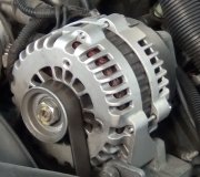
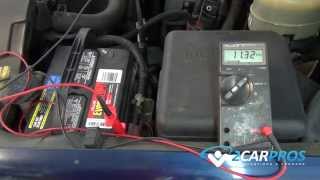
"after disconnecting owner from brown wire I connected a side marker light between brown wire and alternator and grounded it turned power on and it lights up."

Can you be more specific as to exactly which wire or which terminal?

For the door locks, consider starting a new question. That will make it possible to categorize it in such a way as to list it so others researching the same problem can see it. Also, this is a private conversation between just the two of us. As such, none of the other experts will see this new problem or have a chance to reply. That may not get you the help you need.

Some models have a curved slot to stick in an Allen wrench to adjust the linkage for the handles. For your model, I did find this from GM's list of service bulletins:

BODY - DOOR LATCH DIAGNOSTIC PROCEDURES
# PI0011C: Door Latch Diagnostic Procedure - (May 29, 2013)

Subject: Door Latch Diagnostic Procedure Models: 2014 and Prior GM Passenger Cars and Trucks (Excluding Corvette, XLR, CTS Coupe, CTS-V Coupe, DTS)

This PI is being revised to add the 2013-2014 model years and update Warranty Information. Please discard PI0011B.

Condition/Concern

Some customers may comment that the front or rear side door has one or more of the following conditions:

The door will not open from the inside or outside handle.

The door will not unlock with the key fob or electrical switch on the interior door trim.

The door will not unlock with the inside lock knob.

The door will not unlock with the key cylinder.

Note:

Although latches are often replaced for these conditions, malfunctioning parts are often not the actual cause. Please follow this bulletin in order as written.

One possible cause of these symptoms is a condition called "preload, " resulting from incorrect attachment of the outside handle rod to the latch. If the outside handle release lever on the latch is not in the full up position when the rod is attached by the clip on the latch, the latch will not operate correctly.

Another condition causing latch malfunction, especially lock/unlock, is caused by high effort on the inside lock knob. Resistance to the travel of the lock knob may cause the latch not to unlock.

A third condition causing malfunction is the improper or incomplete attachment of the outside handle rod and inside handle rod/cable. If the outside handle rod clip is not completely secured, the clip can come unlatched and the outside handle will not function.

A fourth condition causing malfunction is the improper or incomplete attachment of the wire harness to the side door latch. If the connector is not fully engaged, the power locks, door ajar signal, or other electrical features may not function properly.

The following diagnosis might be helpful if the vehicle exhibits the symptom(s) described above.

Recommendation/Instructions

Note:

Verify the latching function after each step. If the condition exhibited is resolved without completing every step, the remaining steps do not need to be performed.

Perform these preliminary inspections before removing any components:

1. Inspect the inside and outside door handle for debris, that all parts are present and working properly and that they are securely attached.

2. Manually cycle the inside lock knob to check for smooth operation and low efforts (on some newer designed vehicles, the inside handle is used to unlock the door instead of pulling up on the lock knob).

3. Note any differences in lock knob travel between manual function and power lock function. High efforts or reduced power lock travel indicate a lock rod bind condition.

4. For rear doors on which the inside handle will not function, verify that the child security feature is not engaged.

If no issues were found when performing the preliminary inspections, proceed with the following steps.

Note:

Verify the latching function after each step. If the condition exhibited is resolved without completing every step, the remaining steps do not need to be performed.

Photo 1

1. Disengage the door trim, without detaching the inside door handle cable. DO NOT LET THE TRIM PAD HANG FROM THE HANDLE CABLE OR THE WIRE HARNESS.

Photo 2
Photo 3

2. While holding the trim panel close to the installed position, inspect the connections of the inside handle cable to the inside handle and latch. Assure that the cable is not kinked and that the lever on the latch moves when the inside handle is actuated. If the condition persists at this point, disconnect the inside handle cable from the handle and set aside the trim.

3. If the manual lock function had high efforts or was not smooth, check to see if removing the trim panel fixed the condition. Also check for the rod or knob being bound by the rod grommet, side impact foam, water deflector, inner belt seal, or wire harness.

4. Push down on the top of the connector that attaches the wire harness to the latch to verify that it is properly connected. Check for proper function. If the connector had not been fully seated, use the appropriate labor code for the harness.

5. Verify that the key cylinder rod is attached to the key cylinder pawl and the latch. Reattach as required.

6. Verify that the outside handle rod is present, properly attached to the handle and is the correct part.

Photo 4

7. Unlatch the clip holding the outside handle rod to the latch. Make sure the outside handle rod lever on the latch is in the full up position and hard against stop on the latch. While maintaining this lever position, apply a slight upward pressure on the rod while reattaching the rod using a new clip. Pull on the clip slightly to verify that it is secure.

8. Disconnect the electrical connector at the latch, inspect for corrosion and verify the electrical output when actuating the electrical switch on the door trim. If power is lacking, perform electrical diagnostics. Reconnect and assure that the connector is fully seated.
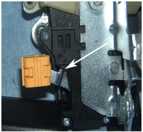
Photo 5

9. Unbolt the latch and remove the latch from the door cavity with the electrical connector still attached. Function the power locks using the switch on the door trim (reattach the switch module to the electrical harness.) Verify that the lock/unlock lever shows full travel (refer to the green arrow in the picture). If the latch properly functions (DO NOT replace latch), properly reassemble in order to correct the bind/attachment issue.

10. If all the above steps have been completed and the latch still does not function correctly, replace the latch.

Chart 6
Was this
answer
helpful?
Yes
No
Saturday, January 9th, 2021 AT 7:55 PM

Please login or register to post a reply.

Sponsored links