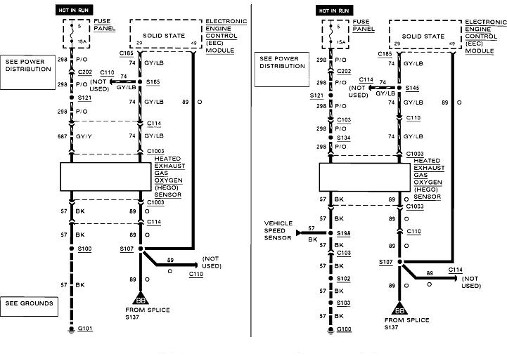
I suspect you are on the wrong wire. The TPS signal wire is gray/white. I added a nifty red arrow pointing to it in the third diagram. The ground wire is brown/white which might look black.
This is confused because logic seems to not apply here. What you are referring to by "signal return" is actually the ground wire for multiple sensors. They don not call it a ground circuit because those wires are not tied to ground, at least not directly. They go to ground through the computer. That way the circuit can be monitored, and it is why you will typically find 0.2 volts on it.
You should find 0.5 to 4.5 volts, (approximately), on the gray/white signal wire. Those are the standard values we use when teaching theory. In practice you might find anything around 0.4 to as high as 1.0 volt at idle. The point of value here is anything outside that range of 0.5 to 4.5 volts is what triggers a diagnostic fault code to be set. If you have no fault code for "TPS voltage high" or "TPS voltage low", the circuit is working properly.
To add even more confusion to this story, the only way to test the signal voltage accurately is to back-probe through the rubber seal around the wire, and the connector must be plugged into the sensor.
First lets get the two easy problems out of the way. If there is a break in the 5.0 volt feed wire or inside the sensor, you will find exactly the same voltage on the signal wire as is on the ground wire, commonly that 0.2 volts I mentioned. That voltage will not change with changing throttle position. That will set the fault code, "TPS voltage too low". If the ground wire has a break, or that terminal is broken inside the sensor, you will find the full 5.0 volts on the signal wire all the time, regardless of throttle position. That will set the code, "TPS voltage too high".
The one that can be confusing is when the signal wire has a break, either in the wire, the terminal in the connector, or a bad spot on the movable contact inside the sensor. Due to all the interconnected circuitry inside the Engine Computer, stray voltage will find its way onto that signal wire from inside the computer. That voltage can "float" to any random value. If that happens to be between 0.5 and 4.5 volts, the computer will accept it and try to run on it. To prevent that, all computer sensor circuits have a "pull-up" resistor or a "pull-down" resistor to force the signal voltage to go to a bad value so it will be detected. That resistor is so big electrically that it has absolutely no effect on the circuit, as long as the sensor is working properly. It's only when there's a break in that signal wire that a voltage appears through that resistor. A pull-down resistor is tied to ground and it puts 0.0 volts on the signal wire when it's broken. By far it is much more common for the engineers to use pull-up resistors, so that's what I'll use here. Those are tied to the carefully-regulated 5.0 volt supply inside the computer. When there's a break in the signal wire, a bad spot in the sensor, or, ... You unplug the sensor, that resistor puts 5.0 volts on that wire, and it gets detected as a defective condition. The computer doesn't know why it's at 5.0 volts, so all it can do is set the "TPS volts too high" fault code. It's up to you to figure out the cause.
The exciting and confusing part is if you turn on the ignition switch, then measure the TPS signal voltage, you're going to find close to 0.5 volts at idle. Now unplug the connector and you'll see it pop up to 5.0 volts, (or 0.0 volts if it uses a pull-down resistor). That is what triggers the fault code, and that is what you would see for TPS voltage displayed on a scanner.
That said, there needs to be even more confusion. This pertains to your question about running with the sensor unplugged. On most models, when a fault code is set related to a sensor, the computer knows it can't rely on its readings, so it disregards them, and "injects" an approximate reading to run on. It won't be perfect, but it will be close. For example, if it sees 5.0 volts on the TPS signal line, and it knows it's only firing the injectors and spark plugs 400 times per minute, it knows pretty well you're not really at wide-open-throttle. It knows you're at idle, and it knows you're not accelerating, so there is no need to enrichen the mixture momentarily. Where this can be confusing is on a few models, mostly GMs from what I've heard in classes, is the scanner will display the voltage the computer is injecting and running on, not what you would see at the sensor with a digital voltmeter. You could erase the fault code for "TPS voltage high", measure a proper 0.5 volts at the sensor, and the fault code immediately sets again when everything looks good. This would only happen with a break in the signal wire so you could have one voltage at the sensor and a different one at the computer and on the scanner.
Also be aware the TPS has about the least effect on engine performance of all the sensors. Much more important than throttle position, it tells the computer the direction of throttle change, and the rate of change. On newer models, some self tests are initiated only at idle or only at brief wide-open-throttle. As for actual throttle position when driving, the other sensors play a more important role in fuel metering calculations.
One culprit you might look closer at is the coolant temperature sensor. Normally temperature sensors have an extremely low failure rate because there is just one part inside them. Ford, however, did have a huge problem in the early 1990's with theirs. The symptoms were erratic idle speed and occasional black smoke from the tail pipe. I had one of these on a 1991 Taurus that we could watch the resistance bounce up and down all over the place with an ohm meter. For all other cars, it is much more common to find corrosion between its terminals and the mating terminals in the connector, and sometimes corrosion between the two terminals in the sensor.
Images (Click to make bigger)
SPONSORED LINKS
Monday, November 12th, 2018 AT 12:43 AM