Modifying a BMW seat?

Tiny
KOBZA
  • MEMBER
  • 2005 BMW 550I
  • 100,000 MILES
Hello,

I'm not working on a car. Rather I'm making a recliner from a 2006 550i seat. My problem is I don't have a schematic or know what the incoming wires to the seat are. The wires going into the seat are pictured below.

I need to know which wires I can ignore and what wires to power to have this seat work outside of the car. Also, what size power supply do I need?
Thursday, May 11th, 2023 AT 1:53 PM

13 Replies

Tiny
JACOBANDNICKOLAS
  • MECHANIC
  • 108,320 POSTS
Hi,

This is a new one for me. LOL You will need a 12v DC power supply. As far as the seat, I need the model year it came from. The 550i was produced from 2014 to 2017.

Let me know and I'll get you the schematics. Confirm if it is the driver's or passenger's side seat.

Take care,

Joe
Was this
answer
helpful?
Yes
No
Friday, May 12th, 2023 AT 7:49 PM
Tiny
KOBZA
  • MEMBER
  • 7 POSTS
Thank you for your prompt reply. Sorry for the delay, I've got an aging father who needed some help. But I'm back now! : )

I picked 550 only because they made me pick a model on the website. It was a 2006 5 series is all I know. For the 12 v power supply do you know how many amps it needs to supply?

Thank you and have a great day!
Was this
answer
helpful?
Yes
No
Tuesday, May 16th, 2023 AT 10:03 AM
Tiny
JACOBANDNICKOLAS
  • MECHANIC
  • 108,320 POSTS
Hi,

No problem. I went with the 525 model. If you look below, I attached the wiring schematic for the driver's seat. It shows the fuse to be a 30amp fuse.

Please keep in mind, without knowing for sure the model it came from, I can't be 100% sure, but I did check a couple 5 series vehicles and they had the same thing.

Let me know if this helps.

Take care,

Joe

See pics below. Note: I had to cut the pic in half to make it readable. I did overlap the two.
Was this
answer
helpful?
Yes
No
+1
Tuesday, May 16th, 2023 AT 7:48 PM
Tiny
KOBZA
  • MEMBER
  • 7 POSTS
This matches what I see from what looks like the power group going into the chair. There's also a big yellow connector with 12 wires going into it. Any ideas what they do?

Looks like I need to buy a 30-amp dc power supply.

Getting closer!
Was this
answer
helpful?
Yes
No
Wednesday, May 17th, 2023 AT 6:06 AM
Tiny
JACOBANDNICKOLAS
  • MECHANIC
  • 108,320 POSTS
Hi,

There are several variations of options, but the closest I can get to 12 appears to be a 10-pin connector. That is for an orthopedic seat. See pic below. Do the wire colors appear to be correct?

Also, pic 2 shows the optional functions.

Let me know.

Joe

See pics below.
Was this
answer
helpful?
Yes
No
+1
Wednesday, May 17th, 2023 AT 7:49 PM
Tiny
KOBZA
  • MEMBER
  • 7 POSTS
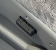
I took some pics to show what I have. The harness pic I fanned the wires out to show them. There are 5 wires that I grouped that seemed to be the power group. There's a brown and a red/green with some smaller wires. They stay together and get plugged into the computer under the seat.

Then there are 12 more wires that leave the harness and go into the yellow connector. Now the yellow/red and yellow/black I followed and they go to the seatbelt. But along with those 2 a red and black also goes to that same seat belt component. They seem to come from the back of the yellow connector, but they don't match any of the wires going into the connector.

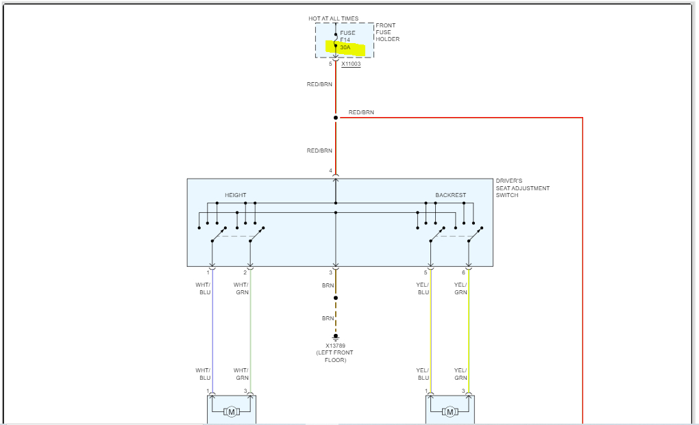
Looking at your diagram I have a few colors that aren't listed like a purple wire going into the yellow connector.

From what I see each component has 4 wires going to it. I'm guessing a power set and a communication set. I'm worried there's a communication with the seat computer or maybe even the car computer that I have to do something about for the seat switches to work.

Thanks again
Was this
answer
helpful?
Yes
No
Thursday, May 18th, 2023 AT 1:12 PM
Tiny
JACOBANDNICKOLAS
  • MECHANIC
  • 108,320 POSTS
The ones that are twisted together are part of the controller area network. I don't think you need to worry about them.

What you need is power to the power supply wire, red/brown. That is power to the switch. The solid brown wire is a ground. You will need to use that to complete the circuit.

Once you have those two things, there are 4 wires that should go to the motors (white/blue, white/green, yellow/blue, and yellow/green).

That (in theory) should make the motors responsive. I do see the wire colors I mentioned in your pic. The modules shouldn't even be needed.

Let me know.

Joe
Was this
answer
helpful?
Yes
No
+1
Friday, May 19th, 2023 AT 9:23 PM
Tiny
KOBZA
  • MEMBER
  • 7 POSTS
I haven't got the power supply yet. Do you think I can just put a car charger on it set at 40 amps or should I wait until it gets here?

A plan is coming together. : )
Was this
answer
helpful?
Yes
No
Saturday, May 20th, 2023 AT 2:33 PM
Tiny
JACOBANDNICKOLAS
  • MECHANIC
  • 108,320 POSTS
Hi,

The charger should work on 12v. I never saw one that you could adjust amperage. Try it and see if it works. It shouldn't hurt anything.

Take care,

Joe
Was this
answer
helpful?
Yes
No
+1
Saturday, May 20th, 2023 AT 9:34 PM
Tiny
KOBZA
  • MEMBER
  • 7 POSTS
Hmmm, I thought I replied to this but don't see it in the chain. I tried the putting 40 amp 12 volt to the red/green and brown wires and got nothing. Any ideas?
Was this
answer
helpful?
Yes
No
Friday, May 26th, 2023 AT 1:03 PM
Tiny
JACOBANDNICKOLAS
  • MECHANIC
  • 108,320 POSTS
If you are taking power directly to the switch, the motors should do something. Does anything happen?

Joe
Was this
answer
helpful?
Yes
No
+1
Sunday, May 28th, 2023 AT 1:21 AM
Tiny
KOBZA
  • MEMBER
  • 7 POSTS
Nothing at all. Hmmmm
Was this
answer
helpful?
Yes
No
Monday, May 29th, 2023 AT 1:18 PM
Tiny
JACOBANDNICKOLAS
  • MECHANIC
  • 108,320 POSTS
Try running power directly to the motors to see if they respond. Maybe the motors are not good, or the switch is faulty.

Let me know.

Joe
Was this
answer
helpful?
Yes
No
+1
Tuesday, May 30th, 2023 AT 8:38 PM

Please login or register to post a reply.

Sponsored links