Hello .. thanks for the donation .. much appreciated
Hope this helps ..let me know
Code 51 and DTC 1260 are the same code
DTC 1260: SUNLOAD SENSOR CIRCUIT OPEN
Turn ignition off. Disconnect sunload sensor 6-pin harness connector C287. Measure resistance between sunload sensor terminals No. 1 and 5. See Fig. 12 . If resistance is more than zero ohms, go to next step. If resistance is zero ohms, replace sunload sensor. Recheck system operation.
Turn ignition on. Press AUTO on EATC panel. Measure voltage between sunload sensor harness connector C287 terminals No. 1 (Brown wire) and No. 5 (Black/Yellow wire). If 4.7-5.1 volts exists, replace RCC module. Recheck system operation. If 4.7-5.1 does not exist, go to next step.
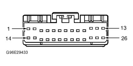
Turn ignition off. Disconnect RCC module 26-pin harness connector C228. Measure resistance of Brown wire between RCC module harness connector C228 terminal No. 6 and sunload sensor harness connector C287 terminal No. 1. See Fig. 3 and Fig. 13 . If resistance is less than 5 ohms, go to next step. If resistance is 5 ohms or more, repair open or high resistance in Brown wire. See WIRING DIAGRAMS . Recheck system operation.
Measure resistance between ground and sunload sensor harness connector C287 terminal No. 5 (Black/Yellow wire). If resistance is less than 5 ohms, replace RCC module. Recheck system operation. If resistance is 5 ohms or more, repair open or high resistance in Black/Yellow wire. See WIRING DIAGRAMS . Recheck system operation.
Fig. 12: Identifying Sunload Sensor Terminals
Courtesy of FORD MOTOR CO.
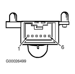
Fig. 13: Identifying Sunload Sensor Harness Connector C287 Terminals
Courtesy of FORD MOTOR CO.
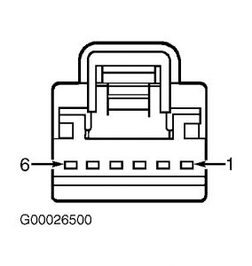
Figure 3.
SPONSORED LINKS
Thursday, March 12th, 2009 AT 5:19 PM

