Hello -
Okay - thanks for the info. . ...I think we got it this time.
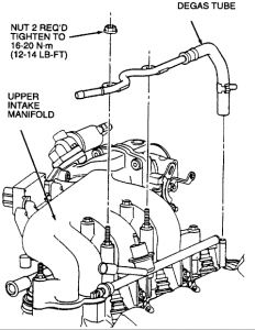
To be safe and ensure I provide you with all the info you need, I have attached info for the upper and the lower intake manifolds, removal and installation.
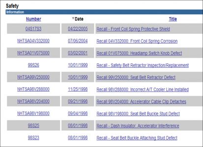
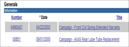
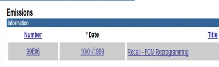
Also, looks like you may have some recalls on your vehicle. The dealer may fix these for free. Please contact the dealer service department, give them the VIN number of your car and have them check on these to see if they apply to you. I attached them last.
Upper Intake Manifold
Notes
Removal
Disconnect battery ground cable.
Remove air cleaner outlet tube.
Remove accelerator cable shield from accelerator cable bracket.
Remove accelerator retracting spring and disconnect accelerator cable and speed control actuator cable from throttle body lever.
Remove two accelerator cable bracket retaining bolts from side of throttle body. Remove accelerator cable bracket and position out of way.
Remove vacuum hose from fuel pressure regulator.
Completely loosen EGR valve to exhaust manifold tube nut at EGR valve.
Disconnect EGR backpressure transducer hoses from the EGR valve to exhaust manifold tube.
Remove crankcase ventilation hose, aspirator vacuum supply hose and evaporative emission return tube from fittings underneath upper intake manifold.
Disconnect engine control sensor wiring connections to Idle Air Control (IAC) valve, Throttle Position (TP) sensor, EGR backpressure transducer and EGR vacuum regulator solenoid.
Drain engine cooling system.
Disconnect degas tube from radiator coolant recovery reservoir and lower intake manifold fitting.
Remove degas tube from the upper intake manifold.
Remove retaining nut and bolts for upper generator brace and remove brace.
Remove engine control sensor wiring bracket from throttle body retaining stud bolt and position engine control sensor wiring out of the way.
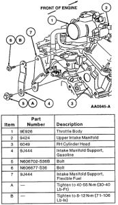
On California Gasoline and flexible fuel equipped vehicles, remove intake manifold support from the throttle body and RH cylinder head.

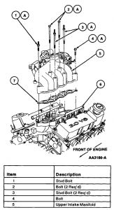
Loosen and remove the upper intake manifold retaining bolts and stud bolts (note location for installation).
Lift and remove upper intake manifold from lower intake manifold.
Discard intake manifold upper gasket.
If required, remove EGR valve, EGR backpressure transducer and EGR vacuum regulator solenoid.
If required, remove the throttle body from the upper intake manifold.
If required, remove the idle air control valve.
Installation
CAUTION: Use care when cleaning gasket material because aluminum gouges easily which forms leak paths. NOTE: Lightly oil all bolt and stud bolt threads with Motorcraft Super Premium 5W30 Motor Oil XO-5W30-QSP meeting Ford specification WSS-M2C153-G prior to installation except those specifying special sealant. Clean and inspect sealing surfaces of intake manifold and throttle body.
Install guide pins (if available).
If removed, install idle air control valve to the upper intake manifold.
If removed, install the throttle body to the upper intake manifold.
If removed, install the EGR valve, EGR backpressure transducer and EGR vacuum regulator solenoid.
Place intake manifold upper gasket on lower intake manifold.
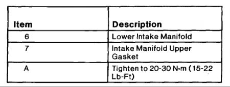
Aligning bolt holes, install upper intake manifold on lower intake manifold. Install stud bolts and retaining bolts. Tighten to 20-30 Nm (15-22 ft. lbs.) .
Install generator brace to upper intake manifold mounting stud and generator mounting bracket. Tighten nut and bolts to 12-20 Nm (9-14 ft. lbs.).
Install intake manifold support to the throttle body and RH cylinder head. Tighten retaining bolts as shown in the illustration.
Install degas tube to the upper intake manifold. Tighten retaining nuts to 16-20 Nm (12-14 ft. lbs.).
Install the engine control sensor wiring bracket onto the throttle body retaining stud bolts.
Connect crankcase ventilation tube, aspirator vacuum supply hose and evaporative emission return tube to fittings underneath upper intake manifold.
Install EGR valve to exhaust manifold tube to EGR valve. Tighten to 30-40 Nm (23-29 ft. lbs.) .
Connect vacuum hose to fuel pressure regulator.
Connect engine control sensor wiring connections to idle air control valve, throttle position sensor, EGR backpressure transducer and EGR vacuum regulator solenoid.
Install accelerator cable bracket to side of throttle body. Tighten retaining bolts to 17 Nm ( 13 ft. lbs.) .
Connect accelerator cable and speed control actuator cable to throttle body lever. Install accelerator retracting spring.
Install accelerator cable shield. Tighten bolts to 1.4 Nm (13 inch lbs.).
Install air cleaner outlet tube.
Connect battery ground cable.
Fill engine cooling system.
Start engine and check for vacuum and exhaust leaks.
NOTE: This adjustment must be performed if the throttle body is removed for any reason and if throttle plate idle adjustment screw position is changed. Check engine idle. Adjust as necessary.
Lower
Notes
Removal
Disconnect battery ground cable.
Drain engine cooling system.
Remove crankcase ventilation tube from valve cover and air cleaner outlet tube.
Remove aspirator hose from air cleaner outlet tube. Remove engine Air Cleaner (ACL) from throttle body and air cleaner outlet tube.
WARNING: COVER FUEL PRESSURE RELIEF VALVE WITH SHOP CLOTH TO PREVENT ACCIDENTAL. FUEL SPRAY INTO EYES. Carefully relieve fuel system pressure at fuel pressure relief valve.
Remove fuel tube safety clips. Disconnect fuel tubes.
Mark locations of vacuum lines and remove.
Disconnect engine control sensor wiring from Camshaft Position (CMP) Sensor, throttle position sensor, idle air control valve, Engine Coolant Temperature (ECT) sensor, ignition coil, water temperature indicator sender unit, EGR backpressure transducer and EGR vacuum regulator solenoid connector.
Disconnect upper radiator hose from water hose connection. After loosening retaining clamp, use a twisting motion on upper radiator hose to loosen hose from water hose connection.
Remove upper intake manifold.
Loosen EGR valve to exhaust manifold tube retaining nut and remove EGR valve to exhaust manifold tube from EGR valve tube to manifold connector.
Disconnect engine control sensor wiring retainers from valve cover stud bolts. Carefully disconnect electrical connections to each fuel injector and position engine control sensor wiring out of the way.
Disconnect heater water hoses.
Remove ignition wires from spark plugs. Remove harness retainers to valve cover stud bolts.
Remove camshaft position sensor.
Remove ignition coil from rear of LH cylinder head.
Remove valve covers.
Loosen cylinder No. 3 intake valve rocker arm seat retaining bolt and rotate rocker arm off of push rod and away from top of valve stem. Remove push rod.
NOTE: Lower intake manifold may be removed with fuel injection supply manifold and fuel injectors in place as an assembly. Remove lower intake manifold retaining bolts using a Torx head socket. Before attempting to remove intake manifold, break seal between intake manifold and cylinder block. Wedge a large pry bar or similar tool between intake manifold and cylinder block. Pry upward on tool using area between water hose connection and transaxle as a leverage point.
Installation
CAUTION: Aluminum components gouge easily which may cause gasket leaks. Always use care when scraping aluminum gasket surfaces. NOTE: Lightly oil all retaining bolt and stud bolt threads with Motorcraft Super Premium 5W30 Motor Oil XO-5W30-QSP or equivalent meeting Ford specification WSS-M2C153-G before installation. Clean mating gasket surfaces of lower intake manifold and cylinder head. Lay a clean cloth or shop cloth in valve tappet valley to catch any gasket material. After scraping, carefully lift cloth from valve tappet valley, preventing any particles from entering oil drain holes or cylinder head. Use a suitable solvent to remove old silicone sealant.
If installing a new lower intake manifold, transfer engine coolant temperature sensor, water thermostat, water hose connection gasket and water hose connection, heater hose elbow and water temperature indicator sender unit to new lower intake manifold.
If removed, install fuel injection supply manifold.
Apply Motorcraft Super Premium 5W30 Motor Oil XO-5W30-QSP or equivalent meeting Ford specification WSS-M2C153-G lightly to fuel injector O-rings before installation.
Install fuel injector into fuel injection supply manifold.
Carefully align fuel injection supply manifold to intake manifold fuel injector bores.
Push one side into place at a time until fuel injection supply manifold clicks into place.
Install fuel injection supply manifold retaining bolts and tighten to 8-12 Nm (71-106 inch lbs.).
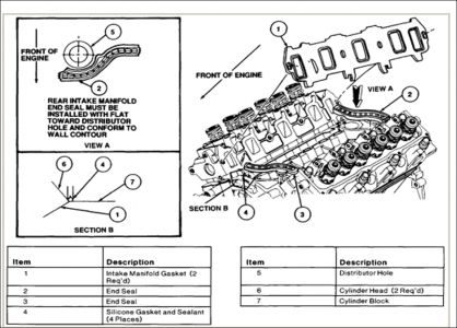
NOTE: Prior to applying sealer, clean sealing surfaces of cylinder block and cylinder head with Metal Surface Cleaner F4AZ-19A536-RA or equivalent meeting Ford specification WSE-M513392-A, to remove all residues that may interfere with the sealer's ability to adhere. Apply a 5-6 mm (1/4-inch) drop of Silicone Gasket and Sealant F7AZ-19554-EA or equivalent meeting Ford specifications WSK-M2G343-A4 to intersection of cylinder block and cylinder head at four corners as shown.
Position intake manifold gasket onto cylinder heads. Align intake manifold gasket locking tabs to provisions on head gaskets as shown.
Install front and rear intake manifold end seals as shown. Secure with retainers.
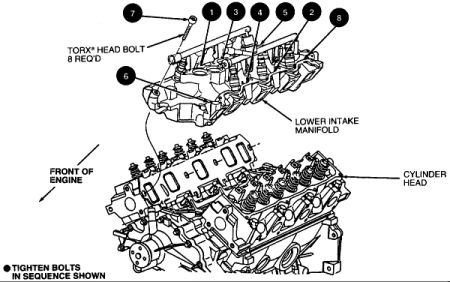
Carefully position lower intake manifold, aligning intake manifold bolt holes, to those in cylinder head. Use care to prevent disturbing silicone sealer which can cause sealing voids.
Install bolts No. 1, 2, 3, and 4 and hand-tighten.
Install remaining bolts and tighten in sequence shown in two steps.
Tighten in numerical sequence to 20-30 Nm (15-22 ft. lbs.).
Tighten again in Sequence to 26-32 Nm (20-23 ft. lbs.).
CAUTION: If a new CKP sensor housing is installed, ALWAYS add the rest of the Engine Assembly Lubricant D9AZ-19579-D or equivalent (pint) meeting Ford specification ESR-M99C80-A to the engine oil by pouring it through the distributor hole onto the camshaft drive gear. Run engine at idle for five minutes prior to driving vehicle. Coat entire drive gear on CMP sensor housing with Engine Assembly Lubricant D9AZ-19579-D or equivalent meeting Ford specification ESR-M99C80-A and install camshaft position sensor.
NOTE: Rocker arm seat must be fully seated into cylinder head and push rod must be fully seated in rocker arm and valve tappet sockets prior to final tightening. Apply Motorcraft Super Premium SAE 5W30 Motor Oil XO-6W30-QSP or equivalent meeting Ford specification WSS-M2C153-G to cylinder No. 3 intake valve, push rod and rocker arm. Install push rod. Move rocker arm into position with push rod and snug rocker arm seat retaining bolt. Rotate crankshaft to position camshaft lobe straight down and away from valve tappet.
Tighten rocker arm seat retaining bolt to 7-15 Nm (6-11 ft. lbs.).
Final tighten rocker arm seat retainer bolt to 26-38 Nm (20-28 ft. lbs.) in any position.
Install valve covers.
Install engine control sensor wiring to each fuel injector. Secure retainers for engine control sensor wiring to valve cover stud bolts.
Install ignition coil to rear of LH cylinder head. Tighten retaining bolts to 40-55 Nm (30-40 ft. lbs.).
Install wire harness retainers to valve cover stud bolts and connect ignition wires to spark plugs and ignition coil.
Install upper intake manifold and new intake manifold upper gasket.
Install EGR valve to exhaust manifold tube from exhaust manifold to EGR valve.
Install fuel tubes.
Install fuel tube safety clips.
Install upper radiator hose and heater water hoses. Tighten retaining clamps securely.
Connect vacuum lines to premarked locations.
Connect engine control sensor wiring to camshaft position sensor, idle air control valve, throttle position sensor, engine coolant temperature sensor, EGR backpressure transducer, EGR vacuum regulator solenoid, ignition coil and water temperature indicator sender unit.
Fill and bleed engine cooling system.
CAUTION: Engine coolant is corrosive to all engine bearing material. Replacing oil after removal of a coolant carrying component prevents damage. Fill crankcase to proper level with Motorcraft Super Premium SAE 5W30 Motor Oil XO-5W30-QSP or equivalent meeting Ford specification WSS-M2C153-G.
Install air cleaner outlet tube to throttle body and engine air cleaner.
Install crankcase ventilation tube to valve cover and air cleaner outlet tube. Install aspirator hose to air cleaner outlet tube.
Connect battery ground cable.
Start engine and check for coolant, oil, fuel and vacuum leaks.
Sunday, December 14th, 2008 AT 1:15 PM