Hi,
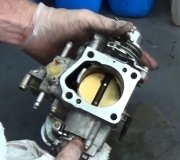
The only thing I noticed that you didn't mention is a fuel filter. Has it been replaced? If so, then either we have a power issue to the pump or a faulty pump. You indicated the carburetor is new. Did the truck run with it in the past? Have you taken it apart to make sure there isn't an issue with the needle valve preventing fuel from entering it?
Here are diagnostics for the fuel delivery system. The pics below correlate with the directions. Take a look through them and let me know if you are comfortable doing it.
____________________________________________
1984 Nissan-Datsun Truck PL720 2WD L4-2389cc 2.4L SOHC (Z24)
Component Tests and General Diagnostics
Vehicle Powertrain Management Fuel Delivery and Air Induction Testing and Inspection Component Tests and General Diagnostics
COMPONENT TESTS AND GENERAL DIAGNOSTICS
NOTE: This test assumes that the vehicle does not start or has an intermittent stalling problem that is fuel related.
Fuel Pump Control Circuit And Operation
pic 1
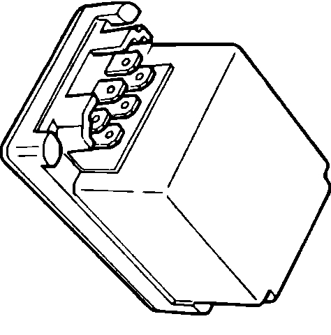
Fuel Pump Control Unit
pic 2
To test the fuel pump, control relay and associated circuit, proceed as follows:
Relay Location
pic 3
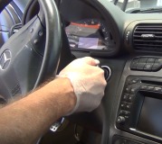
1. With the key in the START position, tap on the fuel pump control unit (located to the right of the glove box) and listen for the sound of the fuel operating.
A. If the fuel pump operates, check the connection at the control unit. If the connections are OK, replace the fuel pump control unit.
B. If the fuel pump does not operate, continue with the remainder of the test.
Fuse Locations
pic 4
Fuel Pump Control Unit
pic 5
2. Check the following fuses: 4, 5 and 6. All of these fuses supply power to the fuel pump control unit.
A. Replace any shorted fuses and recheck fuel pump operation. If the fuses do not have power supplied to them when the key is in the ON position, check the ignition switch and the fuse links at the battery.
3. Turn the key to the ON position.
4. Using a volt meter, back probe the BLUE wire at the control unit.
A. If battery voltage does exist, proceed to next step.
B. If battery voltage does not exist, check for an open in the BLUE wire between the control unit and fuse 6.
5. Using a volt meter, back probe the WHITE wire at the control unit.
A. If battery voltage does exist, proceed to next step.
B. If battery voltage does not exist, check for an open in the WHITE wire between the control unit and fuse 5.
6. Using an ohm meter, back probe the YELLOW/GREEN wire at the control unit.
7. Turn the key to the START position for approximately 20 seconds and check for continuity between the wire and ground.
A. If continuity exists, proceed to next step.
B. If continuity does not exist, check the oil pressure switch (it should close, providing the ground signal once oil pressure builds) also check for continuity between the the oil pressure switch harness terminal and the WHITE wire at the control unit.
8. Turn the key to the OFF position.
Alternator Terminals
pic 6
9. Disconnect the "T" shaped connector on the alternator.
10. Using an ohmmeter, check for continuity between the "L" terminal (leg of the "T") harness connector at the alternator and the WHITE/BLUE wire at the control unit.
A. If continuity exists, proceed to next step.
B. If continuity does not exist, repair the open WHITE/BLUE wire.
11. Reconnect the alternator "T" connector.
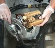
Fuel Pump Location
pic 7
12. Disconnect the fuel pump control unit and the the fuel pump connectors (located on the R.H. Frame rail).
13. Using an ohm meter, check for continuity between the BLACK wire at the control unit connector and ground.
A. If continuity exists, proceed to next step.
B. If continuity does not exist, repair the open BLACK wire.
14. Using an ohm meter, check for continuity between the BLACK wire at the fuel pump connector and ground.
A. If continuity exists, proceed to next step.
B. If continuity does not exist, repair the open BLACK wire.
15. Using an ohm meter, check for continuity between the WHITE/BLACK wire at the control unit connector and the RED wire at the fuel pump.
A. If continuity exists, proceed to next step.
B. If continuity does not exist, repair the open wire between the fuel pump and the control unit (the wire routes through connectors 132M/1C under the carpet below the passengers seat).
Fuel Pump Test
pic 8
16. Using a 12vdc power supply, apply voltage to the fuel pump as shown. Replace the fuel pump if it does not operate.
______________________________
Let me know if this helps or if you have other questions.
Take care and God Bless,
Joe
Images (Click to make bigger)
SPONSORED LINKS
Wednesday, February 24th, 2021 AT 8:02 PM