Hello
There are several things that can cause what you seem to be describing. Review of the fuses for each indicate they are different fuses and relays. Even the steering wheel has a speed control switch.
It would really help if you took the car to Auto Zone or O'Reilly's and have them bring the tester out and have them check the battery, starter and alternator. Your battery was dead which could mean a couple of things. But we need to make sure your alternator is properly charging the battery. Weak electrical input will cause all types of problems. You may have a new battery installed. But if the alternator is not putting out right, you will still have electrical problems. While there, have them check the vehicle for any codes. That would really help out also.
Also, with today's computers in cars, jump starting must be accomplished correctly to prevent damage to electrical components.
For the battery being dead, there was a technical service bulletin out on this. I have attached it for your review. However, it is still important to have the other checks performed. Once accomplished let us know.
I have also attached a few other TSB on the other systems for your review.
Disconnect the negative battery terminal (Figure 1). Attach a jumper wire between the negative battery post and negative battery terminal such that it can be easily attached and unattached like alligator clip ends. Attach a digital multi meter (DMM) as shown. Attach the negative battery terminal to the DMM AMP INPUT. There are typically two AMP inputs on the meter and they are labeled "A" and "mA" (or mA uA). Use the input that is fused for at least 1 amp of current; typically this is the "A" input. Attach the battery negative post to GROUND (GND) or COMMON input of the DMM (Figure 1). Set the DMM mode dial to mA or A (depending on the meter used).
KOL Measurement:
With the jumper wire connected as shown in Figure 1, the meter will show an erroneous reading - ignore it. Wait 30 minutes (so that the vehicle goes to sleep). Then disconnect the jumper wire and read the meter. You may notice the meter reading periodically jumping up in value. That is normal and is the body security module (BSM) or vehicle security module (VSM) polling transmitters and possibly the tire pressure monitoring system (TPMS) transmitters. Use the lower value. If the meter has "average" reading capability, use it to read the average value. For example, a normal reading could be 0.019 A (19 mA) with a momentary periodic jump in the reading to 0.048 A. Use the 0.019 A reading. The 0.048 A reading is due to the BSM (or VSM) momentarily waking up to pole the remote keyless entry (RKE) or TPMS. If you set the DMM for average, you will get a more stable reading of about 0.019 A to 0.020 A.
The maximum average KOL current for a normal functioning vehicle in sleep mode will be no greater than 28 mA (read on the DMM as 0.028 A or 28 mA). A vehicle will be in sleep mode after 30 minutes of no electrical system activity. All KOL measurements are taken while the vehicle is in sleep mode. A KOL measurement of greater than 28 mA is considered a KOL fault/issue. When the vehicle is awake (not in sleep mode) the typical KOL for a normal functioning vehicle is 860 mA +/- 100 mA (read on a meter as 0.86 A or 860 mA).
NOTE IF UNSURE ON HOW TO READ THE DMM CONSULT THE DMM OPERATING MANUAL.
If the vehicle has a KOL issue, expect KOL readings of greater than 0.029A (29 mA) and as high as 0.96A (960mA) after the vehicle is asleep. Perform KOL fault isolation to find the cause of the excess current draw.
Fault Isolation:
Fault isolation for a KOL issue is done by removing a portion of the electrical system and rechecking KOL to see if by removing that portion of the electrical system the KOL reads normal (less than 0.028A). Removal of a portion of the electrical system can be done three different ways:
1. Disconnect one module at a time.
2. Pull fuses out one at a time (this will remove both modules and circuits).
3. Disconnect harnesses at various interconnects (this will remove modules and complete sections of the vehicle harnesses).
To isolate a high KOL issue disconnect a portion of the electrical system, wait 30 minutes, then take a KOL reading. If the new reading is greater than 28 mA, then reconnect the disconnected portion and then disconnect a different portion of the electrical system, wait 30 minutes, then take a KOL reading. Continue this testing until the KOL drops to below 28 mA. The portion of the electrical system removed that causes the KOL drop to normal contains the issue.
Exception - The BSM (or VSM), Cluster, and PCM contain bus termination resisters and should NOT be disconnected from the harness for KOL testing. Isolate these three modules last using the order and method listed:
a. Isolate the PCM using fault isolation method (1) and recheck KOL
b. Isolate the VSM using fault isolation method (2) for fuses F5 and recheck KOL
c. If the high KOL is present after all other modules have been isolated, swap the cluster for a known good cluster and recheck KOL
The high KOL is still present after all modules have been fault isolated, isolate for pinched harness circuits using fault isolation method (3).
NOTE IT IS RECOMMENDED THAT YOU RECONNECT MODULES, FUSES, OR A PORTION OF THE ELECTRICAL SYSTEM PRIOR TO DISCONNECTING ANOTHER.
Removing a portion of the electrical system will cause the KOL to drop slightly. But ONLY the removal of the portion of electrical system with the KOL issue will cause the reading to drop to BELOW 0.028A (28 mA).
For example, a vehicle's KOL is measured to be 0.4A (400 mA). The dual climate control seat module (DCSM) is removed by disconnecting the module. KOL is again measured and found to be 0.34A (or 340 mA). The DCSM is reconnected. Next the power liftgate module (PLGM) is removed by disconnecting the module. KOL is again measured and found to be 0.022A (or 22 mA). The PLGM is the root cause of the issue because the KOL fell below 0.028A (28 mA) once removed. Removal of the DCSM did not cause the KOL to go below NORMAL.
If you use fault isolation method (2) or (3) you will need to further isolate the KOL on the portion of the disconnected electrical system. For example, if you pulled a particular fuse that fuses the radio, climate control head, and steering wheel switches and the KOL dropped to below normal, the problem could be any one of those components on that fuse or the fused circuit. To further isolate, the fuse would be plugged back in and the individual components pulled separately with KOL checked for each component pulled.
ISOLATION HINTS:
If the KOL is greater than 0.6A (600 mA), use fault isolation method (1) starting with the DCSM.
If the KOL is greater than 0.9A (900 mA), use fault isolation method (3). This is probably a short circuit.
WARRANTY STATUS: Information Only
On the power mirrors a TSB also
TSB 06-2-5
02/06/06
POWER FOLDING MIRROR OPERATION
FORD:
2004-2006 F-15O
2005-2006 Expedition
LINCOLN:
2003-2006 Navigator
ISSUE
The 2005-2006 Expedition Limited edition, 2003-2006 Navigator, and the 2004-2006 F-150 King Ranch vehicles have Power Folding Mirrors as a standard feature. Customers may not fully understand the operation of the side mirrors. Some customers have returned for service stating that the mirrors are loose, won't lock, are over extended or won't fully extend. This condition will occur if the mirrors are moved inward/outward manually. The mirrors cannot be manually reset, and must be reset using the mirror switch.
ACTION
Please inform your customers of the power folding mirror operation outlined below, specific to their vehicle type, and provide them with a copy of the normal operating characteristics from their owner's manual.
NOTE IF THE POWER FOLDING MIRRORS ARE FOLDED OR UNFOLDED CONTINUOUSLY (6 TO 10 CYCLES), THE POWER LOCKOUT FEATURE WILL DISABLE THE SYSTEM FOR 2 MINUTES TO PREVENT DAMAGE TO THE POWER FOLD MOTORS. AFTER 2 MINUTES HAVE ELAPSED, NORMAL OPERATION WILL RESUME. IF A CUSTOMER REPORTS INTERMITTENT FUNCTION ON A POWER FOLD MIRROR, ENSURE THAT THE CUSTOMER IS NOT MISTAKING THIS PROGRAMMED 2 MINUTE BREAK FOR DAMAGE BEFORE REPLACING THE MIRROR.
POWER FOLDING MIRROR OPERATION
Power fold the side mirrors in when driving through a narrow space like an automatic car wash.
To Operate The Mirrors:
Navigator
^ Press the solo auto fold mirror switch to fold the mirrors in
^ Press the switch down again to auto unfold the mirrors back out
NOTE ONLY ON THE NAVIGATOR THERE IS AN 8 SECOND DELAY (BETWEEN DEPLOY AND RETRACT)
Expedition
^ Rotate the 4-way mirror adjustment switch to the center position
^ Press the switch down to auto fold the mirrors in
^ Press the switch down again to auto unfold the mirrors back out F-150 King Ranch
^ Rotate the 4-way mirror adjustment switch to the center position
^ Momentarily pull the switch rearward to auto fold the mirrors in
^ Momentarily pull the switch rearward again to auto unfold the mirrors back out
Resetting The Power Folding Mirrors
The mirrors may be moved inward/outward manually; however, if the mirrors are moved manually, they must be reset electrically, by using the mirror switch, to return the mirrors back to their locked positions.
Navigator
^ Press the auto fold mirror switch to fold the mirrors in
^ Wait a short period (8 seconds), press the switch down again to auto unfold the mirrors back out
^ Listen for a loud popping noise, indicating resetting of the mirrors is complete. If a pop is not heard, repeat the procedure until the pop is heard. After resetting, the mirrors will operate normally until they are moved manually again
Expedition
^ Rotate the 4-way mirror adjustment switch to the center position
^ Press the switch down to fold the mirrors in
^ Press the switch down again to unfold the mirrors out
^ Listen for a loud popping noise, indicating resetting of the mirrors is complete. If a pop is not heard, repeat the procedure until the pop is heard. After resetting, the mirrors will operate normally until they are moved manually again
F-150 King Ranch
^ Rotate the 4-way mirror adjustment switch to the center position
^ Momentarily pull the switch rearward to fold the mirrors in
^ Momentarily pull the switch rearward to unfold the mirrors out
^ Listen for a loud popping noise, indicating resetting of the mirrors is complete. If a pop is not heard, repeat the procedure until the pop is heard. After that, the mirrors will operate normally until they are moved again manually
Also the running board have a TSB
Remove the two spool locks from the guide tracks by removing the spool lock retaining bolts (Figure 1) and test the system again. If the system moves freely with the spool locks removed check spool lock or arm track for damage and replace damaged part.
(2) If torque greater than 4.0 Nm (35 lb-in) must still be applied to move the running board, the issue is most likely in the drive arm or idler arm. Remove the running board assembly from the vehicle, refer to Workshop Manual Section 501-08. Remove the four bolts that secure the drive unit to the running board. With bolts removed, manually compare the drag of both the drive arm and idler arm. If drag is excessive in either arm, replace the appropriate arm. Refer to REMOVAL AND INSTALLATION.
REMOVAL AND INSTALLATION
NOTE THE RETRACTABLE RUNNING BOARD MUST BE REMOVED FROM THE VEHICLE IN ORDER TO REPLACE THE IDLER OR DRIVE UNIT. FOR ADDITIONAL INFORMATION, REFER TO WORKSHOP MANUAL SECTION 501-08
When replacing the idler housing and arm assembly, first note the distance from the top of the idler housing and arm to the bottom of the vehicle body (Figure 2). This measurement will be used later to set the height of the retractable running board.
2. Remove the four (4) bolts that secure the drive and idler assemblies to the board (Figure 3).
4. Remove the outer pivot seal (Figure 5).
5. Remove the outer pivot ring clip and washer (Figure 6).
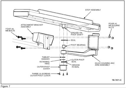
. Before installing the new drive and idler unit, be sure that the seal is present and in the proper orientation, that the bushing is present in the pivot bearing, and that the outer pivot shaft is greased. (See Figure 7 for reference)
7. Install the drive and idler assemblies.
NOTE BE SURE TO INSTALL THE THRUST WASHER BEFORE INSTALLING THE PIVOT RING CLIP, AND BE SURE THERE IS GREASE IN THE PIVOT BEFORE INSTALLING THE OUTER PIVOT SEAL.
8. If installing the idler assembly, be sure to set the height of the idler to the same gap that was measured in Step 2 above.
PARTS BLOCK
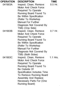
OPERATION/DESCRIPTION/TIME
WARRANTY STATUS:
Eligible Under Provisions Of New Vehicle Limited Warranty Coverage
DEALER CODING
CONDITION
BASIC PART NO. CODE
16B472 41
Oct 17, 2008 at 2:48 PM