Limp mode codes 42 and 51

Tiny
DODGEPODGE
  • MEMBER
  • 1994 DODGE CARAVAN
  • 3.3L
  • 6 CYL
  • 2WD
  • AUTOMATIC
  • 150,000 MILES
Code 42 solenoid error and code 51. What would most likely cause the code 42? Can the shift solenoid and TCM be checked with an ohm meter and a volt meter?
Thursday, November 3rd, 2016 AT 3:42 PM

17 Replies

Tiny
CARADIODOC
  • MECHANIC
  • 33,752 POSTS
42 - Fuel pump or auto shutdown (ASD) relay voltage sensed at controller.
51 - Air/fuel at limit.

These codes are in the Engine Computer. If the transmission is in limp mode, you need to read the codes in the "EATX", Electronic Automatic Transmission Controller.

My guess is you were bypassing the ASD relay as part of your testing, and that sent the twelve volts to a terminal for the Engine Computer at a time it was not supposed to be there, namely, key on, engine not cranking. That is not related to a transmission problem, and I suspect it will not set again once it is erased.
Was this
answer
helpful?
Yes
No
-1
Thursday, November 3rd, 2016 AT 3:52 PM
Tiny
DODGEPODGE
  • MEMBER
  • 74 POSTS
I dont know what you are referring to the ASD? Supposedly these are the transmission codes. Maybe you can explain how these codes would cause limp mode? Thats my main problem. Thats what i'm trying to solve. Thanks
Was this
answer
helpful?
Yes
No
Thursday, November 17th, 2016 AT 8:56 AM
Tiny
CARADIODOC
  • MECHANIC
  • 33,752 POSTS
Those aren't transmission codes. They're Engine Computer codes. You're accessing the wrong computer.

I've never diagnosed a code 42 before, but I am very familiar with the circuit. The automatic shutdown (ASD) relay gets turned on for one second when you turn on the ignition switch, then again during engine rotation, (cranking or running). That relay sends current to the ignition coils, injectors, alternator field, and fuel pump or pump relay. It also sends a signal voltage back to the Engine Computer to verify the relay got turned on. That voltage signal should not be there when the engine isn't rotating. Code 42 says voltage appears at the computer when it shouldn't, and by far the most likely reason for that is from bypassing the ASD relay as part of a diagnostic procedure. Doing that doesn't hurt anything, it won't cause other problems, and that code will self-erase after 50 engine starts. It has no effect on the transmission either.

If you're using a simple code reader, or you're getting the codes from the Check Engine light, neither of those have the ability to get codes from the Transmission Computer. You need a full scanner to do that. I have an old Chrysler DRB2 for my daily drivers. (I'm sitting in a '94 Grand Voyager right now). I also have a newer DRB3 with extra plug-in cards that allows me to use it on all of my cars. You need to find a mechanic with any older scanner so you can access the Transmission Computer. A lot of independent repair shops bought a Chrysler DRB3 because with one of those cards, it will do emissions-related stuff on any brand of car sold in the U.S. Starting with '96 models. That same card gives it the capability to work on '94 to '97 Chrysler vehicles.

Every shop is going to have a scanner that will work on your van. '95 and older models were pretty unsophisticated in terms of computers, and the aftermarket scanners of that era were not horribly expensive. Those shops will also have newer scanners that cost over $10,000.00, but not all of them will work on '95 and older vehicles.
Was this
answer
helpful?
Yes
No
-2
Thursday, November 17th, 2016 AT 10:36 PM
Tiny
DODGEPODGE
  • MEMBER
  • 74 POSTS
These are the codes that a transmission mechanic gave me. He plugged his snap on scanner into the transmission port on the drivers side under the dash. That port only accesses the transmission, and those are the codes he gave me. So I don't understand how you're telling me these are in the ecm. I have an Innova 3140 scanner and when I plug it into the ecm port under the hood all I get is one code for the o2 senser it reads neither rich nor lean and that will not effect the transmission, so how can I check the shift sonenoid ot tcm that they are functioning with only a vom?
Was this
answer
helpful?
Yes
No
Monday, November 21st, 2016 AT 12:00 PM
Tiny
CARADIODOC
  • MECHANIC
  • 33,752 POSTS
You're right. I use a Chrysler DRB3 scanner, and that lists the codes by description, not number. Looking further, I see when they use code numbers, they use the same two-digit numbers for both computers, but naturally they mean different things.

Rather than try to retype everything, I got these instructions from Mitchell ProDemand. I didn't read through everything, but I recognize the drawings as being from a Chrysler diagnostic manual. See how far this gets you.
Was this
answer
helpful?
Yes
No
+1
Monday, November 21st, 2016 AT 5:15 PM
Tiny
DODGEPODGE
  • MEMBER
  • 74 POSTS
Ok I started test 22a it states probe the 2-4 solenoid control ckt. What is ckt?At tcm connector. It doesnt say with key on or off. I'm assuming it doesnt matter either negative or positive to either 47 or 19it reads infinity (open) thats considered obove 5 ohms correct? Then tested 2-4 solenoid betewwen cavity16 and 19 and that reads infinity(open). Then tested between cavity 19 at the tcm connector and pin 8on the sonenoid connector and that read below 5 ohms. Then I removed the trans control relay and was going to test for resistance as in the diagram but I remembered pin D in the diagram is hot all the time? How can resistance be tested if its hot? Dont understand this. The ohm meter will fry. Can you please explain this?
Was this
answer
helpful?
Yes
No
Thursday, December 1st, 2016 AT 1:20 PM
Tiny
CARADIODOC
  • MECHANIC
  • 33,752 POSTS
"Ckt" is "circuit". When you have a diagnostic fault code, they always refer to the entire circuit, never just a single part. In this case, you're testing a solenoid along with all of the wiring, at the same time. When you get acceptable results, you're done, and you can move on. When you get an open circuit, meaning an infinite reading, you need to narrow it down to a break in a wire, a corroded connector terminal, an open solenoid coil, or, as I often do, a bad connection of the meter's probe.

When testing a solenoid circuit, a typical resistance reading will be around one or two ohms, (almost a dead short, meaning 0 ohms). There will always be a little resistance in the wires, and in your meter's leads. Don't get excited if you find six to eight ohms. It's the open circuit you're looking for. "Open" means there's a break somewhere. Resistance values can always go higher and higher, but if you're using a digital volt / amp / ohm meter, 20 meg ohms, (20 million) is the highest most meters will read. LONG before you get anywhere close to that, the circuit will not work because not enough current can get through. Even though the actual amount of resistance can keep going higher, we reach the point where for all practical purposes, it's like there is a break in the circuit, and we call that "infinite".

My concern now is if you're finding two solenoid coils that are open, how likely is that to occur at the same time? If I were doing those tests and found two open coils, I'm fairly confident I would find my meter probes had a bad connection someplace, or a plug with multiple wires was loose or unplugged.

To set your mind at ease, you will not damage a digital ohm meter by applying 12 volts to it. They can withstand that. That's not the case with the older-style pointer-type meters. You're right though that we take resistance readings in circuits that are not powered up.

To add to the confusion, when the procedure tells you to probe a circuit, it is a test designed around Chrysler's DRB3 scanner. That has a volt / ohm meter built in but I've never used it. I have that scanner for my personal vehicles, but I only use these test procedures to direct me to the correct terminals in a connector, then I use my regular ohm meter. When they show the wiring diagram in one of these diagnostic manuals, they only show the wires specific to the circuit in that test. I like to use the regular service manual because it shows everything at once. That works best when I'm already familiar with the circuit. The steps in the diagnostic manuals are better for people who don't understand how the entire system works, and they aren't interested in learning that. The problem with this approach is if there are 20 steps needed to insure you will be led to the cause of the problem, you are guaranteed you'll have to start at step one, and go through every step. That can be very time-wasting for a mechanic experienced with this circuit, but it can be a life-saver for someone who has never seen this circuit before or worked on it.

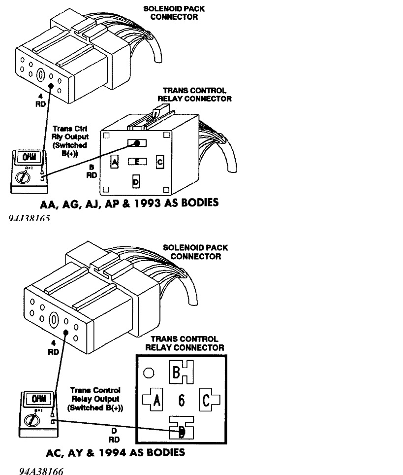
I just read test 22A. The DRB3 scanner already has a ground wire in its cable. What they're having you do is use the scanner's probe to test for continuity to ground on one of the solenoid's wires. That is to test if either wire is shorted to ground, as in a bare wire touching metal engine parts. You don't need to test each wire. If one is grounded, the other one will read as grounded too, through the solenoid. With your ohm meter, place one probe on the terminal specified, and the other probe on a paint-free metal part of the car. The way I like to do it is to place one on the car first, with a clip lead so I don't have to hold onto it, then I place the second probe also on the body, but somewhere else. You should get a reading of 0 ohms, or perhaps a few ohms. That simply proves that both probes are making good contact and are not sitting on some surface dirt or corrosion. Scratch the connections a little if necessary to get a low reading. By the way, the ohm meter should be on the lowest scale to provide the best accuracy. For almost all digital meters that is the 200 ohm scale. That means it will read any resistance value between 0 and 199 ohms. Now that I see the 0 ohms, I have the confidence to continue, knowing the ground probe is making good contact. From then on it's up to the other probe to make good contact, and when it does, I'll get my reading.

You don't want any part of this circuit to be grounded, and if it is not, you will get an infinite reading, which on this scale means it's over 200 ohms. You can switch to a higher scale if you want to momentarily, but you should still see an infinite reading.

The later test is measuring resistance between the two wires going to one of the solenoids. That goes back to the entire "circuit", and my first paragraph. Since you need two meter probes, this is why they're telling you to use a separate ohm meter. That second probe in the DRB3 is in its connecting cable and is hooked to the body sheet metal, electrically. The body, (ground) is not part of this test and is why it can't be done with the DRB3.

I didn't read far enough to see if they want you to take a voltage reading. If they do, 99 percent of them are a voltage at a point in a circuit, in relation to a common point, which simply means ground. Since the DRB3 is already grounded, you just need its single probe to take the reading. When using your voltmeter, use the 20-volt scale, put the black probe on the body, and measure at the point specified with the red probe. If you switch the probes, you'll still get the right value, but with a minus sign.

As long as I'm at it, there is one more thing I should point out. Once you become familiar with measuring the solenoid coils, you might want to measure other things with coils of wire in them. That includes the primary and secondary parts of an ignition coil, the coil in a relay, an injector, or a motor. When current flow is stopped abruptly from flowing through a coil of wire, the collapsing electromagnetic field generates a huge voltage spike. That is very desirable and necessary in an ignition coil, but spikes can damage computers. With motors and injectors, the control circuitry either isn't computer-controlled, or, like with transmission solenoids, the circuitry is so robust, it is relatively immune to those spikes. That's not the case with relays. Their voltage spikes are smaller, but have been known to cause computers to fail or to lock up. To prevent this, almost all relays, except for those in GM vehicles, have a diode across the coil of wire. A diode is a one-way valve for electrical current flow. It is placed across the coil backward, or "reverse biased", so it's like it isn't even there. However, when current flow to that coil is stopped, and the collapsing magnetic field generates a voltage spike, that voltage is the opposite polarity and that puts the diode in the circuit "forward-biased" momentarily. That effectively shorts out the voltage spike and makes it harmless. My reason for sharing this wondrous information is with a few ohm meters, their internal batteries are strong enough to cause the diode to turn on and measure what might appear to be a short. Let me explain.

Most digital meters have a diode test right next to the ohms ranges. You can't measure a diode while it's in a relay because for this test, the coil is shorting it out. If you snip one end of the diode, it is no longer in the circuit and can be measured. The "cathode" has a colored band denoting its polarity, but for this sad story, that is not important. What you should find is with the meter leads connected one way, the meter will read infinite, or open circuit. When you switch the meter leads, you will see a value somewhere between, ... Oh, ... 400 to 700. When any diode is forward biased, it takes a small amount of voltage that must be reached before current starts to flow, and it acts like a short from then on. That voltage is roughly 0.5 volts, give or take a little. That is the voltage the meter is measuring. It is reading to three decimal places, so you might see "632", meaning when 0.632 volts is reached is when current will start to flow. As a further point of interest, high-power diodes, like those used in alternators, have a lower turn-on voltage, typically around 400 millivolts. Small signal diodes, like those used in relays and in computer circuits, typically will be around 650 to 750 millivolts.

The exact value is irrelevant, but it gets even easier when testing a diode. If a diode is shorted, it will act like a piece of wire. Wire has no polarity and as such, the meter will read "0" regardless of which way you connect the meter leads. If it reads shorted one way, there is no need to waste your time measuring it the other way. Next, if you read a good voltage one way, as in "647", the diode has to be good. It isn't open, and it can't be shorted. No need to measure it the other way.

The only time you have to worry about the diode in a relay is when you're building custom circuits. The generic relay will activate with the correct voltage applied across its coil, regardless of polarity. It's when you add the diode that polarity must be observed. The times I've connected one backward, there was nothing to limit current flow through the diode once it turned on, and that excessive current caused it to short, let out the smoke, and from then on it burned open. Once it was open, it was like it wasn't even there. The relay would again operate normally, but there was no diode to suppress those voltage spikes.

I'll be back tomorrow to see if you've made any progress.
Was this
answer
helpful?
Yes
No
Friday, December 2nd, 2016 AT 9:15 PM
Tiny
DODGEPODGE
  • MEMBER
  • 74 POSTS
I dont have a drb or access to one everything I was checking was with a analog ohm meter. From what i've tested and told you so far what would you say the problem is? If I remove the trans relay and test the resistance with a digital ohm meter and get a result, i'm still apprehensive of burning out them ohm meter will that conclude what the problem is?
Was this
answer
helpful?
Yes
No
Saturday, December 3rd, 2016 AT 12:53 PM
Tiny
CARADIODOC
  • MECHANIC
  • 33,752 POSTS
If you WANTED to burn out a digital ohm meter or a solenoid, you're going about it all wrong. To begin with, solenoids draw considerable current because they need to do significant work, so they have to be much stronger than relays. They run on 12 volts. Most ohm meters have internal 6-volt or 9-volt batteries, and neither is capable of providing enough current to turn a solenoid on, let alone burn it out.

Analog ohm meters also need an internal battery to provide the current to whatever is under test. These can be damaged if you apply a voltage to the meter leads while an ohms range is selected. It isn't the circuitry that will be damaged. It's the meter "movement" than can be damaged if you leave it connected too long. The clue is the pointer will go to the left, or it will go way past fully to the right and will be bending in an attempt to go further, (that was humor / sarcasm). The pointer is sitting on an electromagnetic coil, and that coil rotates relative to the amount of current flowing through it. When the pointer is straining to go too far, there is excessive current flowing through the coil. That will overheat it and can warp it or cause it to burn open.

As long as you always use the ohm meter in a circuit that is not connected to a voltage source, you can't damage it.

You must also be aware that we learn best by looking at, playing with, and manipulating parts we can handle. We do not typically learn well by visualizing things. THAT is why mechanics have a hard time learning electrical theory. As such, diagnostic procedures in service manuals are written with that in mind. You must understand that when a step says "5 ohms or less is okay", the world is not going to end if you find 6 ohms. One extreme is 0 ohms. The other extreme is infinite resistance. In that step of the procedure you are going to find 0 or infinite, but I mentioned the wires have some resistance, your meter's leads have some resistance, and the internal calibration of each meter can vary a little. The 5 ohms they mentioned is just so you don't get excited when you don't find exactly "0". You never will, but they don't want you making a wrong conclusion based on that. (Think of the person who gets all excited and calls home because they were able to stuff 16.1 gallons of gas in their car, and the owner's manual says they only have a 16-gallon tank! The values listed in these test procedures are just as general, so don't get "wrapped around the axle" when a reading is just close. Most of the time we're looking for something or nothing, and when you find a number in between, you have to judge which way to read it.

To back up for a moment, I don't believe you ever stated all the symptoms and observations. We jumped into the middle of the last half of the diagnosis without starting at the beginning. Code 51 refers to "a speed error in first gear". That can be caused by a failed speed sensor, failed Transmission Computer, but much more commonly, excessive slippage in one of the transmission's clutch packs. This is where we should be starting. If you have any electrical fault, be it a solenoid, connector terminal, cut wire, etc, that will be detected the instant you turn on the ignition switch, and the system will immediately go into limp mode. You'll begin moving in second gear and you won't have normal acceleration.

Code 42 refers to the 2-4 solenoid circuit but the code isn't specific as to is that an electrical failure that is detected right away, or is it a mechanical failure, as in the computer knows it commanded that solenoid to turn on, but it didn't see a change in state from a pressure switch or sensor. A mechanical problem won't be detected until the circuit is activated.

At this point I'm going to tell you more than I know. If a solenoid is not activating properly to engage second gear, there might be slippage between first and second gears that is detected as that first gear speed error. It would seem awfully unlikely to have two totally unrelated problems at the same time unless a connector was loose or a wiring harness was damaged. I think the code 51 is the faster of the two to diagnose. What you should do is drive the van to see if it starts out in first gear. If it does, the two speed sensors are likely okay electrically. Now, accelerate faster than normal to cause a delay in up-shift timing, then let off the accelerator to cause the transmission to up-shift to second or third gear. Doing it this way takes the load of the clutch packs so no slippage, even the normal slippage won't occur. From that point, if it up-shifts through the gears to fourth gear, you'll know the shift solenoids are working, and you can forget about testing anything related to that.

If it starts out in first gear, but dumps back into limp mode before it should be going into second, suspect a signal is missing from a speed sensor. A missing signal can be caused by an electrical problem, OR a mechanical problem related to a speed sensor, but there was no electrical problem detected in this case. Once the self-test shows the sensor is electrically okay, a missing signal has to be due to a mechanical issue. One common cause is metal filings sticking to the sensor's magnet. That can prevent a good sensor from generating a signal. Some sensors, like some of Chrysler's crankshaft position sensors, need a very precisely-set air gap. THAT is a mechanical issue.

I'm going to let you go for now to try some of my wondrous suggestions. We'll figure out where to go next based on what you find.
Was this
answer
helpful?
Yes
No
Saturday, December 3rd, 2016 AT 10:32 PM
Tiny
DODGEPODGE
  • MEMBER
  • 74 POSTS
Second gear ALL THE TIME. Limp, limp, limp
Was this
answer
helpful?
Yes
No
+1
Sunday, December 4th, 2016 AT 12:46 PM
Tiny
KEN L
  • MASTER CERTIFIED MECHANIC
  • 42,967 POSTS
Yep, this could be a sign that the transmission has an internal seal that is leaking. Did you try to clear the codes by cycling the ignition key on and off five times, this might get it going again.

Without starting the engine, the ignition key, on-off-on-off-on-off-on-off-on-off. Then let it sit and then start the engine and try it.

Please let us know happens so it will help others.

Best, Ken
Was this
answer
helpful?
Yes
No
-1
Sunday, December 4th, 2016 AT 12:53 PM
Tiny
DODGEPODGE
  • MEMBER
  • 74 POSTS
I thought this procedure was to pull codes from the computer. I did as you suggested did'nt do anything
Was this
answer
helpful?
Yes
No
Wednesday, December 7th, 2016 AT 9:27 AM
Tiny
KEN L
  • MASTER CERTIFIED MECHANIC
  • 42,967 POSTS
Hey DODGEPODGE,

Yep the last time this happened in the shop the transmission needed to be rebuilt.

Please let us know what you find so it will help others.

Best, Ken
Was this
answer
helpful?
Yes
No
-1
Wednesday, December 7th, 2016 AT 2:12 PM
Tiny
DODGEPODGE
  • MEMBER
  • 74 POSTS
SORRY I DONT THINK SO !
Was this
answer
helpful?
Yes
No
Thursday, December 8th, 2016 AT 1:09 PM
Tiny
KEN L
  • MASTER CERTIFIED MECHANIC
  • 42,967 POSTS
Okay, what do you think is wrong?
Was this
answer
helpful?
Yes
No
-1
Friday, December 9th, 2016 AT 1:54 PM
Tiny
DODGEPODGE
  • MEMBER
  • 74 POSTS
Ok well do you remember talking about opens in the solenoid ckt? Why would that point to a leaking seal. You never told me how to test the shift solenoid with the connector disconnected? There has to be a way? And why would the codes not clear because of a leaking seal?
Was this
answer
helpful?
Yes
No
Saturday, December 10th, 2016 AT 11:03 AM
Tiny
CARADIODOC
  • MECHANIC
  • 33,752 POSTS
If you know the two terminals for the solenoid in question, use your ohm meter on those two terminals to test for continuity. I never did this so I don't know what "normal" is, but as a general rule, large solenoids like these will have fairly low resistance, as in perhaps 2 to 20 ohms. Smaller relay coils and magnetic sensors' coils will have higher resistance, often higher than 850 ohms. The concern when doing this test is you're looking for a defective condition, (open or shorted), or a good condition, (something). While it is possible, it is extremely rare for a coil to partially short resulting in lower-than-normal resistance, so forgetting that, there are three things to look for.

The first is what I already mentioned, ... A resistance reading. If the service manual says it should be five ohms, don't get excited if you find eight ohms. The manual won't get that picky. Eight ohms means the coil is okay. The value isn't that critical.

The second condition is you find an infinite reading, meaning an open circuit. That will almost always be a wire broken off one of the connector terminals. The assembly is sealed so it must be replaced. You can't get inside to repair the broken wire.

The third test is to take the resistance reading between either terminal and the metal housing or bracket that is bolted to the transmission. That should be infinite. If you find any resistance value there, the coil is grounded somewhere. If it is actually the coil, you'll find 0 ohms. If you find a higher value, as in, ... Oh, ... Hundreds or thousands of ohms, it is more likely transmission fluid has found its way between multiple terminals and has become electrically-conductive. Wash that fluid out with Engine Degreaser or brake parts cleaner.

A better test method is to use a scanner to command the Transmission Computer to put the transmission in each gear. This "actuator" test is available on the Chrysler DRB3 scanner, and most likely on the more expensive aftermarket scanners, like those from Snapon. As I recall, there are pressure switches that respond to the changes in state when a solenoid activates, and you can read those states on the scanner. You don't have to worry about which solenoid / clutch packs engage for each gear. All you have to look at is whether each pressure switch changed in one of the gears. If every switch changed state at some point, every solenoid has to be working.

There are many pressure test ports on the front of the transmission too. You can use a pressure gauge on one port at a time. I have the four pressure transducers that are part of the accessory kit for the DRB3, but I've never used them.

If you're going to do resistance testing, rather than go down to the hard-to-see solenoid connector, measure from the computer's plug. That will include the two wires and their connector terminals in the test. The Transmission Computer is bolted to the passenger side of the firewall. When probing these terminals, be careful to not stick the probe in so far that they stretch those terminals. That can cause intermittent or no connection, and the same fault code.
Was this
answer
helpful?
Yes
No
Saturday, December 10th, 2016 AT 2:20 PM

Please login or register to post a reply.

Sponsored links