MASS AIRFLOW/INTAKE AIR TEMPERATURE (MAF/IAT) SENSOR
Turn ignition off. Disconnect MAF/IAT sensor unit 5-pin connector. Turn ignition on and measure voltage between ground and connector terminal No. 2 (Brown/Pink wire). See WIRING DIAGRAMS article. If battery voltage is present, go to next step. If battery voltage is not present, check for an open or short in Brown/Pink wire between MAF/IAT sensor and fuse (No. 2, 15-amp on Discovery Series II or No. 26, 20-amp on Range Rover) located in engine compartment fuse/relay box. Perform repairs as necessary.
Turn ignition on and measure voltage between ground and MAF/IAT sensor connector terminal No. 4 (Red wire). If 5.0 volts is present, go to next step. If 5.0 volts is not present, check for an open or short in Red wire between MAF/IAT sensor and ECM 52-pin connector C0636 terminal No. 7. Perform repairs as necessary.
Turn ignition off. Check for continuity between ground and MAF/IAT sensor connector terminal No. 3 (Red/Black wire). If continuity exists, go to next step. If continuity does not exist, check for an open or short in Red/Black wire between MAF/IAT sensor and ECM 52-pin connector C0636 terminal No. 9. Perform repairs as necessary.
Turn ignition off and connect MAF/IAT sensor 5-pin connector. Start engine and allow to idle at normal operating temperature. Backprobe MAF/IAT sensor 5-pin connector terminal No. 1 (Gray/Light Green wire) and measure sensor output signal voltage. Output signal voltage should be approximately 0.0-5.0 volts and increase as engine speed and airflow increase. See Fig. 7. If voltage is as specified, go to next step. If voltage is not as specified, replace MAF sensor and retest.
Start engine and allow to idle at normal operating temperature. Backprobe ECM 52-pin connector C0636 terminal No. 34 (Gray/Light Green wire) measure sensor output signal voltage. Output signal voltage should be approximately 0.0-5.0 volts and increase as engine speed and airflow increases. See Fig. 7. If voltage is as specified, go to next step. If voltage is not as specified, check Gray/Light Green wire for an open or short between MAF/IAT sensor and ECM. Check for poor connections, loose terminals, and wires. Perform repairs as necessary.
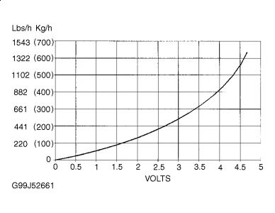
Turn ignition off and connect MAF/IAT sensor 5-pin connector. Start engine and allow to idle at normal operating temperature. Backprobe MAF/IAT sensor 5-pin connector terminal No. 5 (Blue/Green wire) and measure sensor output signal voltage. Output signal voltage should be approximately 0.0-5.0 volts and increase as engine speed and airflow increase. See Fig. 8 table. If voltage is as specified, go to next step. If voltage is not as specified, replace MAF sensor and retest.
Start engine and allow to idle at normal operating temperature. Backprobe ECM 52-pin connector C0636 terminal No. 23 (Blue/Green wire) measure sensor output signal voltage. Output signal voltage should be approximately 0.0-5.0 volts and increase as engine speed and airflow increases. See Fig. 8. If voltage is not as specified, check Blue/Green wire for an open or short between MAF/IAT sensor and ECM. Check for poor connections, loose terminals, and wires. Perform repairs as necessary.
Fig. 7: Intake Air Temperature (IAT) Sensor Output Values
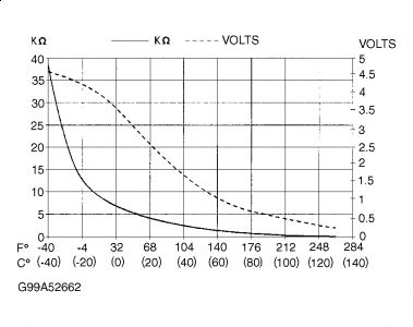
Fig. 8: Mass Airflow (MAF) Sensor Output Voltage
Mar 15, 2010 at 8:49 PM
