Hi tatts20,
Here are the description and procedures.
DTC P0440: EVAP SYSTEM MALFUNCTION OR DTC P0442: EVAP SYSTEM LEAK DETECTED (SMALL LEAK)
Diagnostic Aids
Engine Control Module (ECM) will run EVAP System Leak Monitor when engine coolant temperature at start-up was 150 °F (66 °C) or less, at least 16.75 minutes have passed since engine started or long term fuel trim has stabilized and idle control system has passed diagnostic checks, intake air temperature is more than 9 °F (-13 °C), battery voltage is more than 10.9 volts, engine is idling, vehicle speed is zero MPH, fuel control system is in closed loop, and pressure within EVAP system is within predefined limits. ECM closes Canister Control Valve (CCV) and Purge Solenoid Valve (PSV), then monitors changes in EVAP system pressure. DTC P0440 or P0442 will set if pressure changes indicate system is malfunctioning or leak exists. If test conditions are met, monitor will run only once per drive cycle for about 30 seconds. If test conditions are not met, monitor will not run. Two trip fault.
Check for:
"¢ Fuel filler cap loose or missing.
"¢ Fuel filler cap "O" ring missing or damaged.
"¢ Faulty or damaged fuel filler pipe.
"¢ Leaking, disconnected or plugged fuel vapor lines.
"¢ Fuel in lines due to faulty rollover valve, check valves or stuck closed Canister Close Valve (CCV).
"¢ Canister Close Valve (CCV) clogged, stuck open or closed.
"¢ Improperly installed Purge Solenoid Valve (PSV).
"¢ PSV stuck open or closed.
"¢ Fuel Tank Pressure Sensor (FTPS) malfunction.
"¢ Leaking EVAP canister or catch tank.
Procedure
NOTE:
If any DTCs related to FTPS, CCV or PSV circuits are present, repair those first. Using scan tool, clear DTCs. Drive vehicle with KIA Data Pro connected to OBD-II Data Link Connector (OBD-II DLC) and monitor for pending codes. If DTC P0440 or P0442 returns, perform following procedure.
NOTE:
Record all freeze frame, CID and TID data before disconnecting any connectors or clearing codes.
1. Check fuel filler cap for correct installation and presence of good, correctly installed "O" ring. Test fuel filler cap. It should vent at about 3 psi pressure and about 2 In. Hg vacuum. If fuel filler cap fails test, replace fuel filler cap. If fuel filler cap passes test, go to next step.
2. Check fuel filler pipe for cracks, damage and "O" ring seat deformation. If problem exists, replace fuel filler pipe. If fuel filler pipe is okay, go to next step.
3. Check all fuel vapor hoses and hose clamps between:
"¢ EVAP canister and fuel tank.
"¢ EVAP canister and CCV.
"¢ EVAP canister and PSV.
"¢ PSV and intake manifold.
Also, ensure arrow on PSV is pointing towards intake manifold. If problem exists, repair as necessary. If problem does not exist, go to next step.
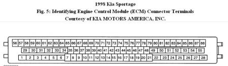
4. Remove fuel filler cap to vent tank. Turn ignition on. Backprobe and measure FTPS output voltage at ECM connector terminal No. 76 (White/Black wire). See Fig. 5 . Voltage should be 2.18-2.82 volts. If voltage is as specified, go to next step. If voltage is not as specified, replace FTPS, then go to next step.
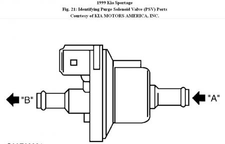
5. Turn ignition off. Reinstall fuel filler cap and tighten. Disconnect hose between PSV and intake manifold at PSV end. Disconnect PSV 2-pin connector. Apply vacuum to PSV port "B". See Fig. 21 . PSV should hold vacuum. Open PSV by jumpering one PSV terminal to
battery positive terminal. Jumper other PSV terminal to battery negative terminal. PSV should click and vacuum should bleed off. Repeat procedure 4-5 times to ensure reliability of results. If PSV is operating reliably as specified, go to next step. If PSV is not operating as specified, or operation is not reliable, replace PSV, then go to next step.
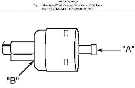
6. Turn ignition off. Restore PSV electrical and vacuum connections. Disconnect hose between EVAP canister and CCV at EVAP canister end. Disconnect CCV 2-pin connector. Blow air into port "A". Air should escape from port "B". See Fig. 22 . Close CCV by jumpering one CCV terminal to battery positive terminal. Jumper other CCV terminal to battery negative terminal. Blow air into port "A". Air should not escape from port "B". Repeat procedure 4-5 times to ensure reliability of results. If CCV is operating reliably as specified, go to next step. If CCV is not operating as specified, or operation is not reliable, replace CCV, then go to next step.
7. Remove check valve from vehicle and verify part No. K01G is stamped on valve. Visually inspect for signs of cracking around mounting boss or in body. Blow air through each port. Check valve should be open with slight restriction in both directions. Check valve diaphragm should pop when air is blown through in direction of arrow on check valve. If check valve is correct part number and operates as specified, go to next step. If check valve is not correct part number or does not operate as specified, replace check valve, then go to next step.
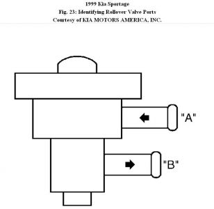
8. Remove rollover valve from vehicle. Holding rollover valve in upright position, blow through ports "A" and "B". Air should only pass from port "A" to port "B" as shown in illustration. See Fig. 23 . When rollover valve is tilted more than 40 ° from vertical in any direction, air should not pass between ports "A" and "B". If rollover valve performs as specified, go to next step. If rollover valve does not perform as specified, replace rollover valve, then go to next step.
9. Install all parts that were removed and connect all connectors and vacuum hoses that were disconnected. Insert "T" fitting in EVAP hose between PSV and EVAP canister. Connect hand pressure pump to "T" fitting. Ensure fuel filler cap is installed and tight. Backprobe and connect jumper wire between ground and ECM connector terminal No. 18 (Blue/Black wire). See Fig. 5 . Backprobe and connect positive lead of DVOM to ECM connector terminal No. 76 (White/Black wire). Connect negative lead of DVOM to ground. Turn ignition on. Using hand pressure pump, apply pressure to system until DVOM (FTPS output voltage) reads about 4 volts. If voltage increases to about 4 volts, go to step 11 . If voltage does not increase to 4 volts, go to next step.
10. Remove fuel filler cap and check for release of pressure. If release of pressure is noticed, replace FTPS. If no release of pressure is noticed, check for clogged vapor lines between PSV and fuel tank. If clogging is found, repair or replace clogged section of line. If clogging is not found, check for fuel in EVAP canister. If fuel is found in EVAP canister, check for stuck closed CCV and repair as necessary.
11. Clamp off hose to hand pressure pump and monitor FTPS output voltage for one minute. After one minute, voltage drop should be 100 millivolts or less. If voltage drop is within specifications, go to step 13 . If voltage drop is not within specifications, go to next step.
12. Remove clamp from hose to hand vacuum/pressure pump. Pressurize system to maximum 2 psi and clamp off hose again. Locate leaks with R-134a leak detector and repair as necessary.
13. Remove jumper wire between ground and ECM connector terminal No. 18 (Blue/Black wire). FTPS output voltage should drop within 15 seconds to within 10 percent of base voltage read in step 4) . If voltage drops as specified, go to next step. If voltage does not drop as specified, recheck EVAP lines, check valve and rollover valve, CCV and EVAP canister for obstructions. When obstruction is located, repair as necessary and repeat steps 7) - 13) .
14. Connect jumper wire between ground and ECM connector terminal No. 18 (Blue/Black wire). Using hand pressure pump, apply pressure until DVOM (FTPS output voltage) reads about 4 volts. Backprobe and connect jumper wire between ECM connector terminal No. 36 (Red/White wire) and ground. FTPS output voltage should drop within 30 seconds to within 10 percent of base voltage read in step 4) . If voltage drops as specified, go to next step. If voltage does not drop as specified, recheck PSV operation and check EVAP canister for obstructions. Repair as necessary and repeat step 14) .
15. Clear codes. Perform Readiness Drive Cycle. Ensure engine coolant temperature is less than 150 °F (65.5 °C) before starting drive cycle. After completing test, check for any pending codes.
Page 3 of 3
SELF-DIAGNOSTICS - TESTS -1999 Kia Sportage
3/11/2010
Nov 2, 2010 at 12:32 PM

