Try this for pulling codes, if anything other than 55 flashes, write it down and post here. Test these cicuits.
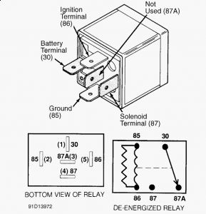
MODULES Theft Alarm Module (Cherokee & Grand Cherokee) 1. Turn ignition switch to ACC position 3 times and leave in ACC position to activate Security Alarm Module (SAM) self-diagnostics. If headlights do not flash, go to step 3). 2. If horn does not sound twice, go to step 9). If exterior lights do not flash, go to step 10). If parking lights and taillights do not flash, go to step 11). If horn sounds twice and headlights, parking lights and taillights flash, go to step 12). 3. Check for battery voltage at terminal No. 1 of security alarm module relay (located in relay center under glove box). If less than battery voltage is present, repair open to fuse No. 7 (15- amp) and retest. If system does not operate properly, go to next step. If battery voltage is present, go to step 5). If system operates properly, stop test procedure. 4. Using an ohmmeter, check continuity between security alarm module relay terminal No. 2 and headlight feed wires. If continuity exists, replace security alarm module relay and retest. If continuity does not exist, repair open in wiring circuit as necessary and retest. 5. Check for battery voltage at security alarm module relay terminal No. 3. If battery voltage is not present, repair open in wiring circuit as necessary. If battery voltage is present, go to step 7). If less than battery voltage is present, turn ignition switch to RUN position, then turn ignition off. 6. Check continuity between security alarm module relay pins No. 3 and 5. If continuity does not exist, replace security alarm module relay and retest. If continuity exist, check continuity between security alarm module terminal No. 7 (located behind center cluster bezel on instrument panel) and security alarm module relay pin No. 5. If continuity exists, replace security alarm module and retest. If continuity does not exist, repair open in wiring circuit as necessary and retest. 7. Turn ignition switch to RUN position, then turn ignition off. Check continuity between security alarm module relay pin No. 3 and ground. If continuity does not exist, repair open in wiring circuit as necessary and retest. If continuity exists, replace security alarm module relay with known good relay. If system does not operate properly, go to next step. If system operates properly, stop test procedure. 8. Using an ohmmeter, check continuity between security alarm module relay terminal No. 2 and headlights. If continuity exists, replace security alarm module relay and retest. If continuity does not exist, repair open in wiring circuit as necessary and retest. 9. Turn ignition switch to RUN position, then turn ignition off. If horn does not operate properly, NOTE: For identifying circuits referred to in testing, see appropriate wiring diagram in WIRING DIAGRAMS article in this section. NOTE: If SECURITY light comes and remains on with ignition on, the Chrysler Collision Detection (CCD) bus communication with the PCM has been lost. After servicing vehicle ensure that system operates properly. A malfunctioning anti-theft system may keep engine from starting. check horn system for malfunction. Repair as necessary and retest. If horn operates properly, check continuity between security alarm module terminal No. 12 and horn relay connector. If continuity exists, replace security alarm module. If continuity does not exist, repair open in wiring circuit and retest. 10. Turn ignition switch to RUN position, then turn ignition off. If flash-to-pass does not operate, check and repair fuse No. 7 (15-amp) as necessary and retest. If flash-to-pass operates, check for battery voltage at security alarm module pin No. 21. If battery voltage is present, replace security alarm module. If voltage is less than battery voltage, repair open in wiring circuit to fuse and retest. 11. Check for battery voltage at lamp outage module pin No. 6. If battery voltage is present, repair open in light system. If voltage is less than battery voltage, check for battery voltage at security alarm module pin No. 14. If battery voltage is present, repair open in wiring circuit between security alarm module and rear lights. If less than battery voltage is present, replace security alarm module. 12. Ensure all doors and liftgate are closed. Verify that SECURITY light is flashing. If SECURITY light is not flashing, check bulb and wiring harness. Repair or replace as necessary. If bulb and wiring are okay, replace security alarm module and retest system. 13. If SECURITY light is flashing, turn ignition switch to OFF position. Remove illuminated entry relay from vehicle. Relay is located on a bracket behind instrument panel. 14. Check theft alarm switches by opening and closing doors and liftgate. Replace switch(es) or repair wiring harness as necessary. If switches are okay, check hood switch by opening and closing hood. 15. Replace hood switch or repair wiring harness as necessary. If hood switch is okay, unlock (with key) each front door and liftgate one at a time to test disarm switches. Replace switch(es) or repair wiring harness as necessary and retest system. 16. If disarm switches are okay, cycle power door locks to lock position and then unlock. If power door locks do not operate properly, replace door lock switch(es), lock/unlock relay(s) or repair wiring harness as necessary. Retest system. 17. If power door locks operate properly, lock and unlock vehicle with keyless entry transmitter. If power door locks do not operate properly, replace keyless entry transmitter, receiver or repair wiring harness as necessary and retest system. 18. If keyless entry system operates properly, turn ignition switch to ON position and wait 30 seconds. If SECURITY light comes on and stays on, repair or replace CCD bus and wiring as necessary and retest system. If SECURITY light remains off, theft alarm system is operating properly. NOTE: A functional PCM that has been used in a vehicle equipped with theft alarm system CANNOT be used in another vehicle that is NOT equipped with theft alarm system.
1/30/2010
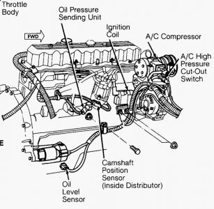
http://www.ondemand5.com/mric/common/asp/Article.aspx?MOD=REPART&YEAR=19 ...CRANKSHAFT POSITION SENSOR 1. Disconnect crankshaft position sensor. Connect ohmmeter across sensor terminal No. 2 (Black/Light Blue wire) and terminal No. 1 (Gray/Black wire on Cherokee and Wrangler; Red/Light Green wire on Grand Cherokee). 2. Ohmmeter should indicate an open circuit. Replace sensor if reading is not as specified. Also see appropriate crankshaft position sensor tests in G - 2.5L & 4.0L TESTS W/ CODES article in this section. MANIFOLD ABSOLUTE PRESSURE (MAP) SENSOR 1. Inspect MAP sensor vacuum hose connections at throttle body and sensor. Replace or repair vacuum hose if necessary. 2. Turn ignition on with engine off. Using DVOM, check MAP sensor output voltage. Connect DVOM to MAP sensor terminal "B" (Dark Green/Red wire on Cherokee and Wrangler; Red/White wire on Grand Cherokee) and ground. Terminal identification letters are marked on sensor body. 3. Output voltage should be 4-5 volts. Voltage should drop to 1.5-2.1 volts with a hot engine operating in Neutral and at idle speed. Also check for output voltage at PCM wiring harness terminal No. 1 on Cherokee and Wrangler or terminal No. 5 on Grand Cherokee. If voltage is not as previously specified, repair wiring harness as necessary. 4. With ignition on, check MAP sensor supply voltage at sensor connector terminal "C" (Violet/White wire). Supply voltage should be 4.5-5.5 volts. Also check for supply voltage at PCM wiring harness terminal No. 6. If supply voltage is not as specified, repair wiring harness if necessary. 5. Check continuity of MAP sensor ground circuit at sensor connector terminal "A" (Black/Light Blue wire) and PCM wiring harness terminal No. 4. Check continuity of MAP sensor ground circuit at sensor connector terminal No. 1 (Black/Light Blue wire) and PCM wiring harness terminal No. 4. Repair wiring harness if necessary. 6. Check continuity of MAP sensor ground circuit between PCM wiring harness terminals No. 4 and 11. If ohmmeter indicates an open circuit, go to next step. If ground connection is okay, replace PCM. 7. Check for defective sensor ground connection. Connection is located on right side of engine block, at oil dipstick tube mounting block. Repair connection as necessary. NOTE: If terminal No. 4 has a short circuit to 12 volts, correct this condition before replacing PCM. If necessary, perform appropriate MAP sensor tests in G - 2.5L & 4.0L TESTS W/ CODES article in this section. CAMSHAFT POSITION SENSOR 1. Use an analog voltmeter. DO NOT remove distributor connector from distributor. Insert voltmeter leads into backside of distributor wiring harness connector to make contact with terminals. Ensure connector is not damaged when inserting test probes. 2. Insert positive voltmeter lead into camshaft position sensor signal output circuit (Tan/Yellow wire on Cherokee and Wrangler; Gray/Black wire on Grand Cherokee) at distributor wiring harness connector. Insert negative voltmeter lead into ground circuit (Black/Light Blue wire) at distributor wiring harness connector. Set voltmeter to 15-volt DC scale. 3. With distributor cap removed, manually rotate engine until pulse ring enters sync signal generator on camshaft position sensor. Distributor rotor should be at 9 o'clock position. Turn ignition switch to ON position. With pulse ring positioned in the sync signal generator, reading should be approximately 5 volts. 4. If no voltage is present, check voltmeter leads for good connections. If connections are okay and there is still no voltage, check for voltage at supply circuit (Orange wire on Cherokee and Wrangler; White/Black wire on Grand Cherokee). 5. If no voltage is present at supply wire, remove PCM connector. Check voltage at PCM pin No. 7 and ground with wiring harness connected. PCM is located on left side of engine compartment. If there is no voltage at PCM, see appropriate camshaft position sensor circuit tests in G - 2.5L & 4.0L TESTS W/ CODES article in this section. 6. If voltage is present at supply wire, replace camshaft position sensor. If voltage is present at PCM pin No. 7, but not at supply wire, check continuity of supply wire between the distributor connector and the PCM. If no continuity exists, repair wiring harness as necessary. 7. If supply wire is okay, check continuity between camshaft position sensor signal output wire at the distributor connector and PCM pin No. 44. If no continuity exists, repair wiring harness as necessary. 8. If camshaft position sensor signal output wire is okay, check continuity between ground circuit wire at the distributor connector and ground. If no continuity exists, repair wiring harness as necessary. If ground wire is okay, go to next step. 9. While observing voltmeter, crank engine. Voltmeter needle should fluctuate from 0-5 volts while the engine is cranking. This verifies that camshaft position sensor in distributor is operating properly and that a sync pulse signal is being generated. If voltmeter does not fluctuate, replace camshaft position sensor.
1/30/2010
http://www.ondemand5.com/mric/common/asp/Article.aspx?MOD=REPART&YEAR=19 ...
Jan 30, 2010 at 8:12 AM