No spark? - Ignition switch wiring diagram

Tiny
J.STIEG
  • MEMBER
  • 1996 JEEP CHEROKEE
Electrical problem
1996 Jeep Cherokee 6 cyl Four Wheel Drive Automatic

I am trying to troubleshoot a no spark condition on a 96 Jeep cherokee. There is no spark coming out of the coil and seems to have voltage going to it. Coil had been replaced and no change. What should I check first?
Wednesday, October 27th, 2010 AT 5:12 PM

27 Replies

Tiny
KHLOW2008
  • MECHANIC
  • 41,815 POSTS
Hi j.stieg,

Here are the diagnostic procedures for no start conditions.

TEST NS-1A - QUALIFYING NO START CONDITION

1. Turn ignition off. Disconnect spark plug cable at spark plug No. 1. Connect cable terminal to a spark plug tester. Connect spark plug tester to engine ground. Go to next step.

CAUTION:When checking for spark, consider 1-2 sparks as a no-spark condition.

2. While cranking engine for 10 seconds, observe for spark. If a good spark occurs, perform TEST NS-2A
. If a good spark does not occur, reconnect spark plug cable and go to next step.

3. Turn ignition off. Disconnect ignition secondary cable from distributor. Connect cable terminal to a spark plug tester. Connect spark plug tester to engine ground. Go to next step.

4. While cranking engine for 10 seconds, observe for spark. If a good spark occurs, replace distributor cap, rotor or cables as necessary and perform TEST VER-1A
. If a good spark does not occur, go to next step.

5. Turn ignition off. Disconnect other end of ignition secondary cable from ignition coil. Using an external ohmmeter, check resistance between both ends of ignition secondary cable. If resistance is more than 15,000 ohms, replace ignition secondary cable and perform TEST VER-1A. If resistance is 15,000 ohms or less, go to next step.

6. Remove distributor cap and observe distributor rotor while cranking engine. If rotor does not turn, repair distributor drive system as necessary and perform
TEST VER-1A. If rotor turns, go to next step.

7. Reinstall distributor cap and ignition secondary cable. Disconnect ignition coil connector. Inspect connector and terminals for damage. Repair connector and terminals as necessary and perform TEST VER-1A. If connector and terminals are okay, go to next step.

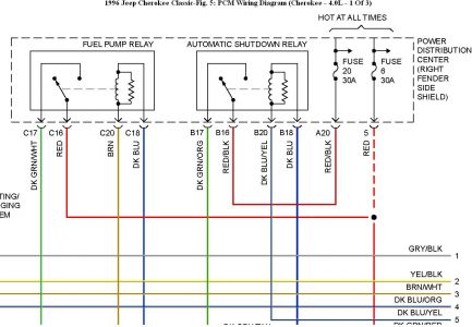
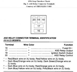
8. Turn ignition on. Using scan tool in voltmeter mode, check voltage on ignition coil connector, ASD relay output circuit (Dark Green/Orange wire). Using scan tool, actuate generator field. If voltage is 10 volts or less, repair open ASD relay output circuit and perform
TEST VER-1A. If voltage is more than 10 volts, go to next step.

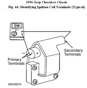
9. Turn ignition off. Using an external ohmmeter, check resistance across ignition coil primary terminals. See
Fig. 44. If resistance is not 0.95-1.20 ohms, replace ignition coil and perform TEST VER-1A. If resistance is as specified, go to next step.

10. Check resistance across ignition coil primary and secondary terminals. See Fig. 44. If resistance is not 11,300-15,300 ohms, replace ignition coil and perform
TEST VER-1A. If resistance is as specified, go to next step.

11. Disconnect PCM Black connector. Inspect connector and terminals for damage. Repair connector and terminals as necessary and perform TEST VER-1A. If connector and terminals are okay, go to next step.

12. Using scan tool in ohmmeter mode, check resistance of PCM Black connector, ignition coil driver circuit (Gray wire). If resistance is less than 5 ohms, repair short to ground in ignition coil driver circuit and perform TEST VER-1A. If resistance is 5 ohms or more, go to next step.

13. Using an external ohmmeter, check resistance of ignition coil driver circuit (Black/Gray wire at ignition coil connector) between PCM Black connector and ignition coil connector. If resistance is more than 5 ohms, repair open ignition coil driver circuit and perform TEST VER-1A. If resistance is 5 ohms or less, go to next step.
Check valve timing. Correct valve timing as necessary and perform TEST VER-1A. If valve timing is okay, replace PCM and perform TEST VER-1A.


https://www.2carpros.com/forum/automotive_pictures/192750_IgnitionCoil96CherokeeFig44_1.jpg


Was this
answer
helpful?
Yes
No
+4
Thursday, October 28th, 2010 AT 9:27 AM
Tiny
J.STIEG
  • MEMBER
  • 352 POSTS
Thanks for info. I made it to step 8 and and there was no power for the coil. I had a helper turn the ignition on and off several times and there dint seem to be any activity and did not hear the ASD or fuel pump relay come on. Do you think there is something wrong here. Do you have a wiring diagram or what should I check next? Thanks
Was this
answer
helpful?
Yes
No
+1
Thursday, October 28th, 2010 AT 2:06 PM
Tiny
KHLOW2008
  • MECHANIC
  • 41,815 POSTS


https://www.2carpros.com/forum/automotive_pictures/192750_ASDRelay96Cherokee_1.jpg


At the ASD relay, if voltage is not present at B16, check fuse # 20 ( 30 A) If fuse is good, there is an open between the fuse and relay.
Was this
answer
helpful?
Yes
No
+9
Friday, October 29th, 2010 AT 9:08 AM
Tiny
J.STIEG
  • MEMBER
  • 352 POSTS
Yes, there is voltage at b16, and there is voltage at the relay coil. Does not seem to be a PCM ground signal for relay, what would cause that?
Was this
answer
helpful?
Yes
No
+1
Friday, October 29th, 2010 AT 11:47 AM
Tiny
KHLOW2008
  • MECHANIC
  • 41,815 POSTS
Check the PCM terminal C3, Dark Blue/Yellow wire continuity to the relay. If continuity is good, the PCM is faulty causing the non grounding.
Was this
answer
helpful?
Yes
No
+3
Friday, October 29th, 2010 AT 12:03 PM
Tiny
J.STIEG
  • MEMBER
  • 352 POSTS
I did an ohms check and the harness tested good for ASD relay. I also checked the coil and it is in good condition. I checked the other components cam and crank but could not complete test because there was no positive 8v supply coming from PCM, or ground if I remember correctly. Also on day one I tried to scan the OBDII but it said linking error, I check for positive voltage at pin 16 and pin 4 and 5 were grounded. Is there any thing in the ignition that would cause the PCM to be inoperative for ASD cam and crank signals? Thanks for all your help
Was this
answer
helpful?
Yes
No
+3
Tuesday, November 2nd, 2010 AT 8:32 AM
Tiny
KHLOW2008
  • MECHANIC
  • 41,815 POSTS
The link error indicates either the scan tool is not compatibel or you have a problem with the PCM or wiring circuit.


https://www.2carpros.com/forum/automotive_pictures/192750_ASDRelay96CherokeeFig03_1.jpg


From the diagram, do you have battery voltage at terminal 16 at all times?

Does terminal # 18 has battery voltage when ignition switch is turned on?
Was this
answer
helpful?
Yes
No
+4
Tuesday, November 2nd, 2010 AT 9:56 AM
Tiny
J.STIEG
  • MEMBER
  • 352 POSTS
Yes, terminal 18 has power and 16 has power at all times.
Was this
answer
helpful?
Yes
No
Tuesday, November 2nd, 2010 AT 11:17 AM
Tiny
KHLOW2008
  • MECHANIC
  • 41,815 POSTS
Terminal # 20 is linked to # C3 of PCM.

With igniton turned on and if you have battery voltage at terminal C3, PCM does not recognise the presence of voltage meaning the PCM is faulty.
Was this
answer
helpful?
Yes
No
Tuesday, November 2nd, 2010 AT 11:34 AM
Tiny
J.STIEG
  • MEMBER
  • 352 POSTS
There is no positive/or negative voltage at terminal 20.
Was this
answer
helpful?
Yes
No
+1
Tuesday, November 2nd, 2010 AT 2:27 PM
Tiny
KHLOW2008
  • MECHANIC
  • 41,815 POSTS
Terminal # 20 should have nothing. You need to test from PCM or with relay plugged in.
Was this
answer
helpful?
Yes
No
+2
Tuesday, November 2nd, 2010 AT 6:50 PM
Tiny
J.STIEG
  • MEMBER
  • 352 POSTS
Terminal # 20 has got to have ground signal if the relay is going to work. So if I get nothing at #20 is it safe to say the PCM is bad with a wire harness that has good continuity from ASD relay to PCM. Thanks for your help.
Was this
answer
helpful?
Yes
No
+1
Tuesday, November 2nd, 2010 AT 10:24 PM
Tiny
KHLOW2008
  • MECHANIC
  • 41,815 POSTS
If the PCM is not grounding terminal #20, then yes, it most likely is a faulty PCM.
Was this
answer
helpful?
Yes
No
+3
Wednesday, November 3rd, 2010 AT 7:40 AM
Tiny
J.STIEG
  • MEMBER
  • 352 POSTS
I put in a PCM and it started right up. Thanks for your technical support, I was able to get right to the problem with your help.
Was this
answer
helpful?
Yes
No
+1
Monday, November 8th, 2010 AT 8:44 PM
Tiny
KHLOW2008
  • MECHANIC
  • 41,815 POSTS
Glad to know you have fixed the problem.

Thank you for using 2CarPros.

Have a nice day.
Was this
answer
helpful?
Yes
No
+5
Tuesday, November 9th, 2010 AT 6:25 AM
Tiny
STEVE ORCHARD
  • MEMBER
  • 4 POSTS
  • 1989 JEEP CHEROKEE
  • 6 CYL
  • 4WD
  • AUTOMATIC
  • 297,000 MILES
I am the original owner of this high mileage vehicle and the ignition wire melted at the starter relay, replaced section of wire inserted in line fuse to protect wire and replaced starter relay. Fuse would blow intermittently, checked ignition wire to ignition switch and replaced ignition switch. It worked fine for a day and then started blowing the in line fuse again, used 20 and 30 amp fuses wire would probably melt without the fuse. Do you have any ideas what else I should look at.
Was this
answer
helpful?
Yes
No
Monday, December 7th, 2020 AT 12:27 PM (Merged)
Tiny
JDL
  • MECHANIC
  • 16,098 POSTS
Hi, thanks for the donation. Your talking about fusible links and not fuses? I looked at wiring info for starter relay, There are several fusible links, only one, has anything to do with starter relay, fusible link F--green. The other links, just grab battery voltage at that point, for other circuits. The battery feed to the switch/load side of relay, doesn't show any protection. The feed to coil side of relay, does have protection, that circuit is to energize the relay. Was it the green wire, at the starter relay, that melted?
Was this
answer
helpful?
Yes
No
Monday, December 7th, 2020 AT 12:27 PM (Merged)
Tiny
STEVE ORCHARD
  • MEMBER
  • 4 POSTS
Yes it is the green wire at the starter relay about six inches long and then it has a factory splice to the red ignition wire, the splice maybe a fuseable link I am not sure. When the green wire melted the first time I installed a in line fuse holder to protect that wire until I resolve the problem.
Was this
answer
helpful?
Yes
No
Monday, December 7th, 2020 AT 12:28 PM (Merged)
Tiny
JDL
  • MECHANIC
  • 16,098 POSTS
One database showed the info below, I'm trying to be sure which green wire, because there are two?


https://www.2carpros.com/forum/automotive_pictures/170934_jeep_starter_relay_1.jpg

Was this
answer
helpful?
Yes
No
Monday, December 7th, 2020 AT 12:28 PM (Merged)
Tiny
STEVE ORCHARD
  • MEMBER
  • 4 POSTS
It is the green wire that goes from the starter relay through the fuseible link and transitions to the red wire that goes to the ignition switch.
Was this
answer
helpful?
Yes
No
Monday, December 7th, 2020 AT 12:28 PM (Merged)

Please login or register to post a reply.

Sponsored links