Hi,
If the smoke is white, chances are it is burning engine coolant. It burns white when it enters the combustion chamber.
Here are directions for replacing the head gasket. Once the heads are off, you should have them checked to see if they are warped or damaged in any way.
Next, if I was replacing the head gaskets, I would also replace the timing belt and all associated components and the water pump at the same time.
Here are directions for cylinder head removal and replacement. The attached pictures correlate with the directions.
____________________________________
2002 Subaru Impreza WRX Sedan F4-2.0L DOHC Turbo
Procedures
Vehicle Engine, Cooling and Exhaust Engine Cylinder Head Assembly Service and Repair Procedures
PROCEDURES
REMOVAL
1. Remove the V-belt.
2. Remove the crankshaft pulley.
3. Remove the belt cover.
4. Remove the timing belt assembly.
5. Remove the camshaft sprocket.
6. Remove the intake manifold.
7. Remove the bolt which installs the A/C compressor bracket on cylinder head.
8. Remove the camshaft.
Pic 1
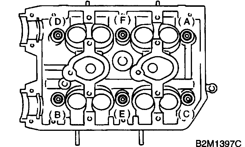
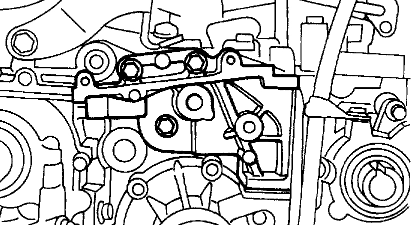
9. Remove the cylinder head bolts in alphabetical sequence shown in the figure.
CAUTION: Leave bolts (A) and (D) engaged by three or four threads to prevent the cylinder head from failing.
Pic 2
10. While tapping the cylinder head with a plastic hammer, separate it from cylinder block. Remove the bolts (A) and (D) to remove the cylinder head.
11. Remove the cylinder head gasket.
CAUTION: Do not scratch the mating surface of cylinder head and cylinder block.
12. Similarly, remove the right side cylinder head.
INSTALLATION
1. Install the cylinder head and gaskets on cylinder block.
CAUTION:
Use new cylinder head gaskets.
Be careful not to scratch the mating surface of cylinder head and cylinder block.
2. Tighten the cylinder head bolts.
A. Apply a coat of engine oil to washers and bolt threads.
B. Tighten all bolts to 29 Nm (3.0 kgf-m, 22 ft-lb) in alphabetical sequence. Then tighten all bolts to 69 Nm (7.0 kgf-m, 51 ft-lb) in alphabetical sequence.
C. Back off all bolts by 180° first; back them off by 180° again.
Pic 3
d. Tighten the bolts (A) and (B) to 34 Nm (3.5 kgf-m, 25 ft-lb).
Pic 4
e. Tighten the bolts (C), (D), (E) and (F) to 15 Nm (1.5 kgf-m, 11 ft-lb).
F. Tighten all bolts by 80° to 90° in alphabetical sequence.
CAUTION: Do not tighten the bolts more than 90°.
G. Further tighten all bolts by 80° to 90° in alphabetical sequence.
CAUTION: Ensure the total "re-tightening angle" [in the two previous steps] do not exceed 180°.
3. Install the camshaft.
4. Install the A/C compressor bracket on cylinder head.
5. Install the intake manifold.
6. Install the camshaft sprocket.
7. Install the timing belt assembly.
8. Install the belt cover.
9. Install the crankshaft pulley.
10. Install the V-belt.
__________________________________________________________
Here are the directions for replacing the timing belt. You will need this to make sure timing is correct before you try starting it.
2002 Subaru Impreza WRX Sedan F4-2.0L DOHC Turbo
Timing Belt Replacement
Vehicle Engine, Cooling and Exhaust Engine Service and Repair Procedures Disassembly and Assembly Timing Belt Replacement
TIMING BELT REPLACEMENT
REMOVAL
1. TIMING BELT
a. Remove the V-belt.
B. Remove the crankshaft pulley.
C. Remove the belt cover.
Pic 5
1 of 4
pic 6
2 of 4
pic 7
3 of 4
pic 8
4 of 4
d. Remove the timing belt guides. (MT vehicle)
e. If the alignment mark and/or arrow mark (which indicates rotation direction) on timing belt fade away, put new marks before removing the timing belt as follows:
pic 9
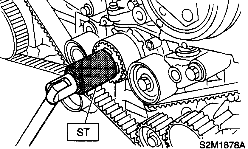
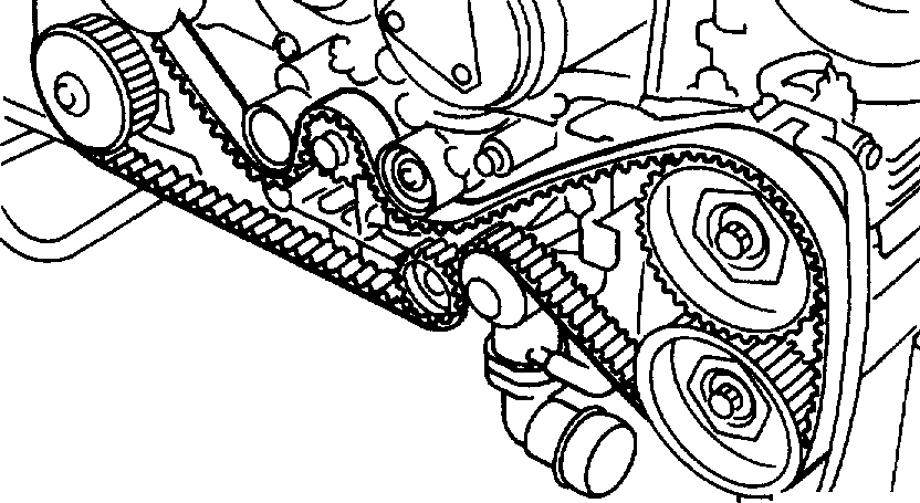
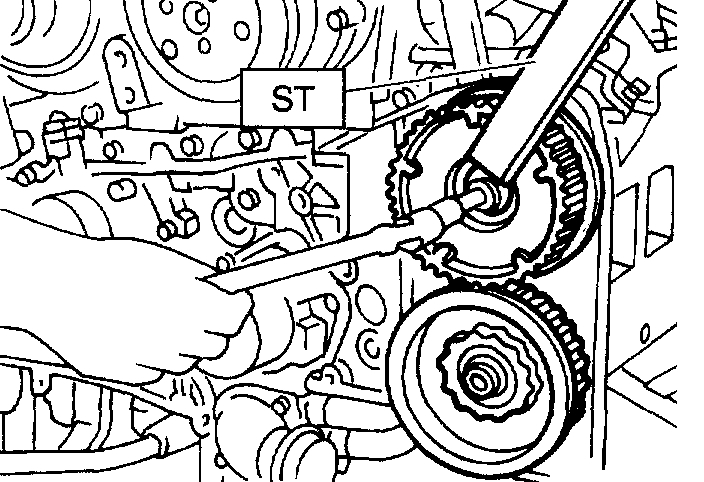
1. Turn the crankshaft using ST, and align alignment marks on crankshaft sprocket, left-hand intake camshaft sprocket, left-hand exhaust camshaft sprocket, right-hand intake camshaft sprocket and right hand exhaust camshaft sprocket with notches of belt cover and cylinder block.
ST 499987500 CRANKSHAFT SOCKET
pic 10
1 of 2
pic 11
2 of 2
2. Using white paint, put alignment and/or arrow marks on the timing belts in relation to the sprockets.
Pic 12
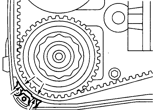
Z1: 54.5 tooth length
Z2: 51 tooth length
Z3: 28 tooth length
pic 13
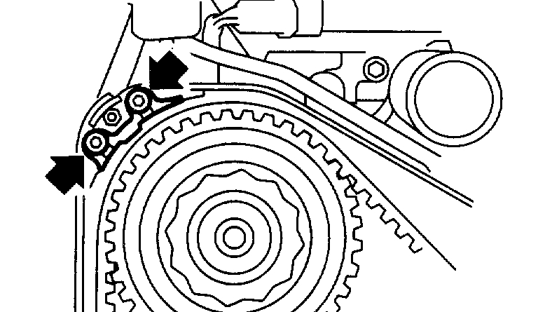
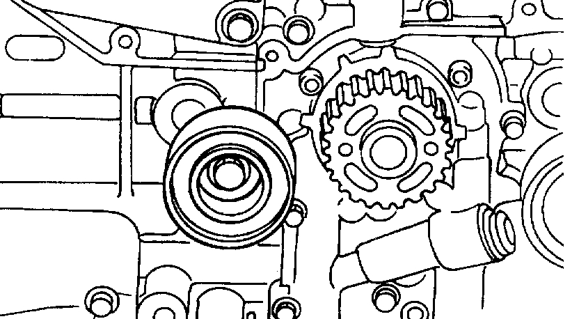
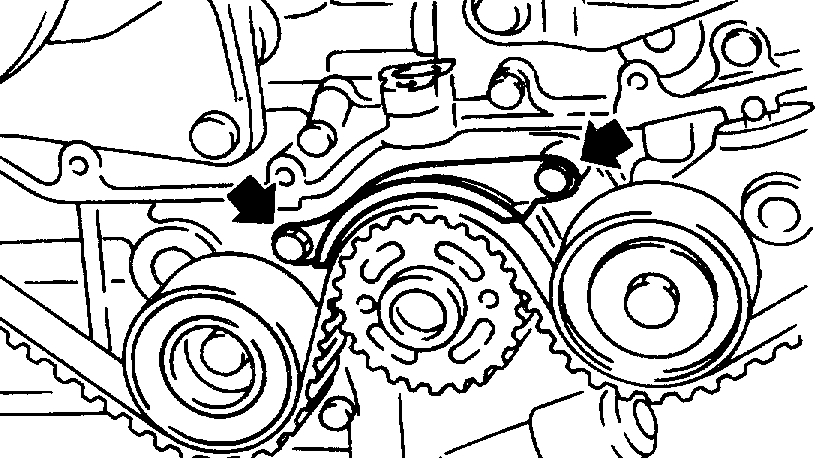
f. Remove the belt idler (A).
G. Remove the timing belt.
CAUTION: After the timing belt has been removed, never rotate the intake and exhaust, camshaft sprocket. If the camshaft sprocket is rotated, the intake and exhaust valve heads strike together and valve stems are bent.
2. BELT IDLER AND AUTOMATIC BELT TENSION ADJUSTER ASSEMBLY
pic 14
a. Remove the belt idler (B) and (C).
Pic 15
b. Remove the belt idler No. 2.
Pic 16
c. Remove the automatic belt tension adjuster assembly.
INSTALLATION
1. AUTOMATIC BELT TENSION ADJUSTER ASSEMBLY AND BELT IDLER
a. Preparation for installation of automatic belt tension adjuster assembly:
CAUTION:
Always use a vertical type pressing tool to move the adjuster rod down.
Do not use a lateral type vise.
Push the adjuster rod vertically.
Be sure to slowly move the adjuster rod down applying a pressure of 294 N (30 kgf, 66 lbs.).
Press-in the push adjuster rod gradually taking more than three minutes.
Do not allow press pressure to exceed 9,807 N (1,000 kgf, 2,205 lbs.).
Press the adjuster rod as far as the end surface of the cylinder. Do not press the adjuster rod into the cylinder. Doing so may damage the cylinder.
Do not release the press pressure until stopper pin is completely inserted.
1. Attach the automatic belt tension adjuster assembly to the vertical pressing tool.
Pic 17
2. Slowly move the adjuster rod down with a pressure of 294 N (30 kgf, 66 lbs.) Until the adjuster rod is aligned with the stopper pin hole in the cylinder.
Pic 18
3. With a 2 mm (0.08 inch) diameter stopper pin or a 2 mm (0.08 inch) (nominal) diameter hex bar wrench inserted into the stopper pin hole in the cylinder, secure the adjuster rod.
Pic 19
b. Install the automatic belt tension adjuster assembly.
Tightening torque: 39 Nm (4.0 kgf-m, 28.9 ft. Lbs.)
pic 20
c. Install the belt idler No. 2.
Tightening torque: 39 Nm (4.0 kgf-m, 28.9 ft. Lbs.)
pic 21
d. Install the belt idler.
Tightening torque: 39 Nm (4.0 kgf-m, 28.9 ft. Lbs.)
2. TIMING BELT
a. Preparation for installation of automatic belt tension adjuster assembly.
B. Crankshaft and camshaft sprocket alignment.
Pic 22
1. Align mark (A) on the crankshaft sprocket with mark on the oil pump cover at cylinder block.
Pic 23
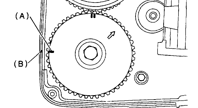
2. Align single line mark (A) on the right-hand exhaust camshaft sprocket with notch (B) on belt cover.
Pic 24
3. Align single line mark (A) on the right-hand intake camshaft sprocket with notch (B) on belt cover. (Make sure double lines (C) on intake camshaft and exhaust camshaft sprockets are aligned.)
pic 25
4. Align single line mark (A) on left-hand exhaust camshaft sprocket with notch (B) on belt cover by turning the sprocket counterclockwise (as viewed from front of engine).
Pic 26
5. Align single line mark (A) on left-hand intake camshaft sprocket with notch (B) on belt cover by turning the sprocket clockwise (as viewed from front of engine). Ensure double lines (C) on intake and exhaust camshaft sprockets are aligned.
6. Ensure camshaft and crankshaft sprockets are positioned properly.
CAUTION:
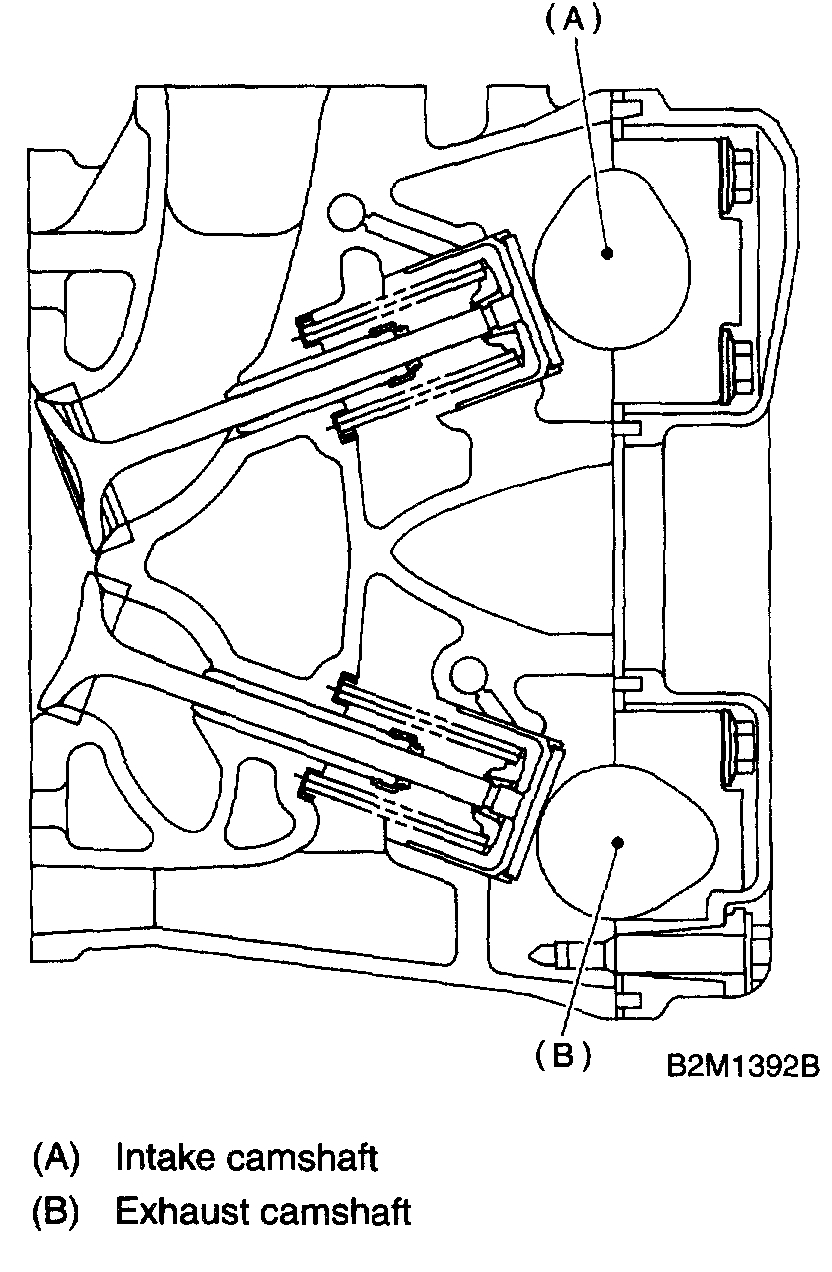
pic 27
Intake and exhaust camshafts for this DOHC engine can be independently rotated with the timing belts removed. As can be seen from the figure, if the intake and exhaust valves are lifted simultaneously, their heads will interfere with each other, resulting in bent valves.
When the timing belts are not installed, four camshafts are held at the "zero-lift" position, where all cams on camshafts do not push the intake and exhaust valves down. (Under this condition, all valves remain unlifted.)
When the camshafts are rotated to install the timing belts, #2 intake and #4 exhaust cam of left-hand camshafts are held to push their corresponding valves down. (Under this condition, these valves are held lifted.) Right-side camshafts are held so that their cams do not push valves down.
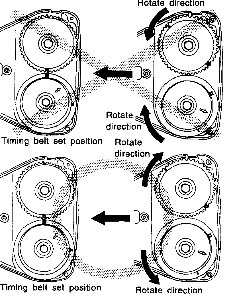
Left-hand camshafts must be rotated from the "zero-lift" position to the position where the timing belt is to be installed at as small an angle as possible, in order to prevent mutual interference of intake and exhaust valve heads.
Pic 28
Do not allow the camshafts to rotate in the direction shown in the figure as this causes both intake and exhaust valves to lift simultaneously, resulting in interference with their heads.
Pic 29
c. Installation of timing belt
pic 30
Align the alignment mark on the timing belt with marks on the sprockets in the alphabetical order shown in the figure. While aligning marks, position the timing belt properly.
CAUTION:
Disengagement of more than three timing belt teeth may result in interference between the valve and piston.
Ensure the belt's rotating direction is correct.
D. Install the belt idlers.
Tightening torque: 39 Nm (4.0 kgf-m, 28.9 ft. Lbs.)
pic 31
CAUTION: Make sure that the marks on the timing belt and sprockets are aligned.
E. After ensuring that the marks on the timing belt and sprockets are aligned, remove the stopper pin from tensioner adjuster.
F. Install the timing belt guide. (MT vehicle)
1. Temporarily tighten the remaining bolts.
Pic 32
1 of 4
pic 33
2 of 4
pic 34
3 of 4
pic 35
4 of 4
2. Check and adjust clearance between the timing belt and timing belt guide.
Clearance: 1.0 ±0.5 mm (0.039 ±0.020 inch)
pic 36
1 of 4
pic 37
2 of 4
pic 38
3 of 4
pic 39
4 of 4
3. Tighten the remaining bolts.
Tightening torque: 9.8 Nm (1.0 kgf-m, 7.2 ft. Lbs.)
g. Install the belt cover.
H. Install the crankshaft pulley.
I. Install the V-belt.
INSPECTION
1. TIMING BELT
a. Check the timing belt teeth for breaks, cracks, and wear. If any fault is found, replace the belt.
B. Check the condition of back side of belt; if any crack is found, replace the belt.
CAUTION:
Be careful not to let oil, grease or coolant contact the belt. Remove quickly and thoroughly if this happens.
Do not bend the belt sharply.
Pic 40
Bending radius: h 60 mm (2.36 inch) or more
2. AUTOMATIC BELT TENSION ADJUSTER
a. Visually check the oil seals for leaks, and rod ends for abnormal wear or scratches. If necessary, replace the automatic belt tension adjuster assembly.
CAUTION: Slight traces of oil at rod's oil seal does not indicate the a problem.
B. Check that the adjuster rod does not move when a pressure of 294 N (30 kgf, 66 lbs.) Is applied to it. This is to check adjuster rod stiffness.
C. If the adjuster rod is not stiff and moves freely when applying 294 N (30 kgf, 66 lbs.), Check it using the following procedures:
1. Slowly press the adjuster rod down to the end surface of the cylinder. Repeat this motion 2 or 3 times.
2. With the adjuster rod moved all the way up, apply a pressure of 294 N (30 kgf, 66 lbs.) To it. Check the adjuster rod stiffness.
3. If the the adjuster rod is not stiff and moves down, replace the automatic belt tension adjuster assembly with a new one.
CAUTION:
Always use a vertical type pressing tool to move the adjuster rod down.
Do not use a lateral type vise.
Push the adjuster rod vertically.
Press-in the push adjuster rod gradually taking more than three minutes.
Do not allow press pressure to exceed 9,807 N (1,000 kgf, 2,205 lbs.).
Press the adjuster rod as far as the end surface of the cylinder. Do not press the adjuster rod into the cylinder. Doing so may damage the cylinder.
D. Measure the extension of rod beyond the body. If it is not within specifications, replace with a new one.
Pic 41
Rod extension: H 5.7 ±0.5 mm (0.224 ±0.020 inch)
3. BELT TENSION PULLEY
a. Check the mating surfaces of timing belt and contact point of adjuster rod for abnormal wear or scratches. Replace the belt tension pulley if faulty.
B. Check the belt tension pulley for smooth rotation. Replace if noise or excessive play is noted.
C. Check the belt tension pulley for grease leakage.
4. BELT IDLER
a. Check the idler for smooth rotation. Replace if noise or excessive play is noted.
B. Check the outer contacting surfaces of idler pulley for abnormal wear and scratches.
C. Check the idler for grease leakage.
_________________________________________
Here are the directions for water pump replacement. I recommend this because the timing belt will need removed to do it in the future, and when replacing the head gaskets, the belt will already be off.
2. TURBO MODEL
WARNING: The radiator is pressurized. Wait until engine cools down before working on the radiator.
1. Set the vehicle on the lift.
Pic 42
2. Disconnect the ground cable from the battery.
3. Lift-up the vehicle.
4. Remove the under cover.
5. Drain the engine coolant completely.
6. Remove the radiator under cover.
7. Disconnect the connectors from the radiator main fan and sub fan motors.
Pic 43
8. Remove the bolt which installs water by-pass pipe of oil cooler onto oil pump.
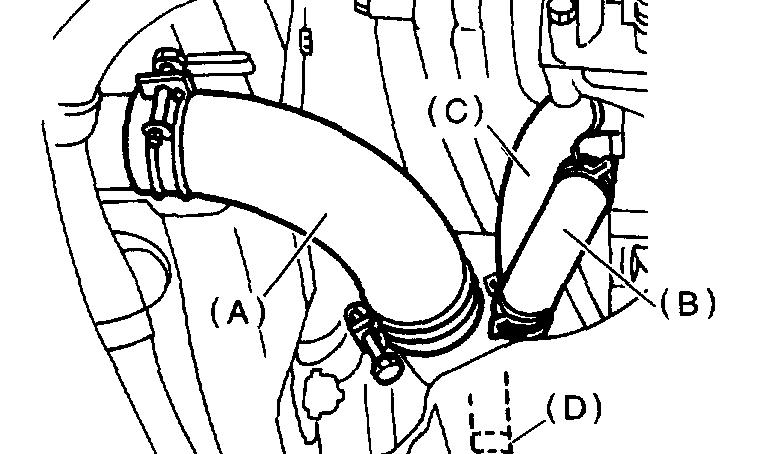
Pic 44
9. Disconnect the radiator outlet hose (A) and heater hose (B) from the water pump.
10. Disconnect the water by-pass hose (C) and oil cooler hose (D).
11. Lower the vehicle.
12. Disconnect the overflow hose.
Pic 45
13. Remove the reservoir tank.
14. Remove the radiator main fan and sub fan assemblies.
15. Remove the V-belts.
16. Remove the timing belt.
Pic 46
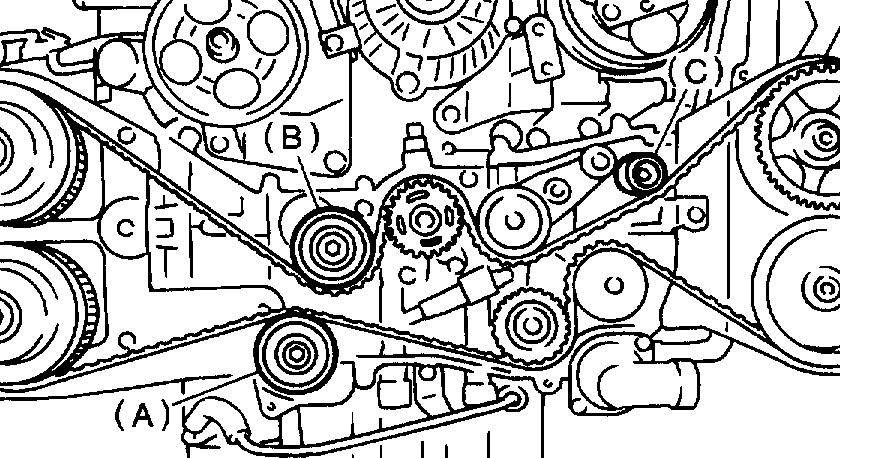
17. Remove the automatic belt tension adjuster (A).
18. Remove the belt idler (B).
19. Remove the belt idler No. 2 (C).
20. Remove the camshaft position sensor.
Pic 47
21. Remove the left-hand camshaft sprockets by using ST.
ST 499207400 CAMSHAFT SPROCKET WRENCH
pic 48
22. Remove the tensioner bracket.
Pic 49
23. Remove the left-hand belt cover No. 2.
24. Disconnect the heater hose from the water pump.
Pic 50
25. Remove the water pump.
__________
Install
2. TURBO MODEL
1. Install the water pump onto the left-hand cylinder head.
CAUTION:
Replace gasket with a new one.
Pic 51
When installing water pump, tighten bolts in two stages in alphabetical sequence as shown in figure.
Tightening torque:
First: 12 Nm (1.2 kgf-m, 8.7 ft. Lbs.)
Second: 12 Nm (1.2 kgf-m, 8.7 ft. Lbs.)
pic 52
2. Install the tensioner bracket.
Tightening torque: 25 Nm (2.5 kgf-m, 18.1 ft. Lbs.)
pic 53
3. Install the left-hand belt cover No. 2.
Tightening torque: 5 Nm (0.5 kgf-m, 3.6 ft. Lbs.)
pic 54
4. Install the left-hand camshaft sprockets by using ST.
ST 499207400 CAMSHAFT SPROCKET WRENCH
Tightening torque: 98 Nm (10.0 kgf-m, 72.4 ft. Lbs.)
5. Install the camshaft position sensor.
Pic 55
6. Install the belt idler No. 2 (C).
7. Install the belt idler (B).
8. Install the automatic belt tension adjuster (A) which has a tension rod held by a pin.
Tightening torque: 39.4 Nm (4.0 kgf-m, 28.9 ft. Lbs.)
9. Install the timing belt.
10. Install the V-belts.
11. Install the radiator main fan and sub fan motor assemblies.
Pic 56
12. Install the reservoir tank.
13. Connect the overflow hose.
14. Lift-up the vehicle.
Pic 57
15. Connect the radiator outlet hose (A) and heater hose (B) to the water pump.
16. Connect the water by-pass hose (C) and oil cooler hose (D).
Pic 58
17. Install the bolt which installs water by-pass pipe onto the oil pump.
18. Connect the connectors to radiator main fan and sub fan motors.
19. Install the radiator under cover.
20. Install the under cover.
21. Lower the vehicle.
Pic 59
22. Connect the battery ground cable.
23. Fill coolant.
__________________________________
Let me know if this helps or if you have other questions.
Take care,
Joe
Images (Click to make bigger)
Saturday, December 28th, 2019 AT 6:42 PM