Front right axle replacement

Tiny
DUWHOP31
  • MEMBER
  • 1999 ISUZU TROOPER
  • 3.5L
  • 6 CYL
  • 4WD
  • AUTOMATIC
  • 160,000 MILES
I need to know what I need to do or remove to replace the front right axle. I have the right front tire off, brake caliper, hub lock and nut all the way to the spindle knuckle.
Monday, May 6th, 2019 AT 11:09 AM

7 Replies

Tiny
JACOBANDNICKOLAS
  • MECHANIC
  • 108,328 POSTS
Welcome to 2CarPros.

Here are the directions for removal of front drive axles. It's more than the typical design. The attached pictures correlate with the directions.

___________________________________

Front
Vehicle Transmission and Drivetrain Drive Axles, Bearings and Joints Axle Shaft Assembly Service and Repair Procedures Front
FRONT

pic 1

DISASSEMBLY
- Jack up the vehicle and support it using jack stands.
- Remove the tire, and wheel.
- Remove the drain bolt to drain differential oil.

NOTE:

pic 2

During the work, be sure that the differential case is supported by the jack.
Remove the brake caliper fixing bolt and hang the caliper.
Remove the antilock brake system speed sensor. (If equipped with antilock brake system).

1. Hub assembly (Disc, back plate and knuckle)
- Remove the locking hub.
- Disconnect the knuckle and the suspension arm.
2. Steering link and arm assembly.
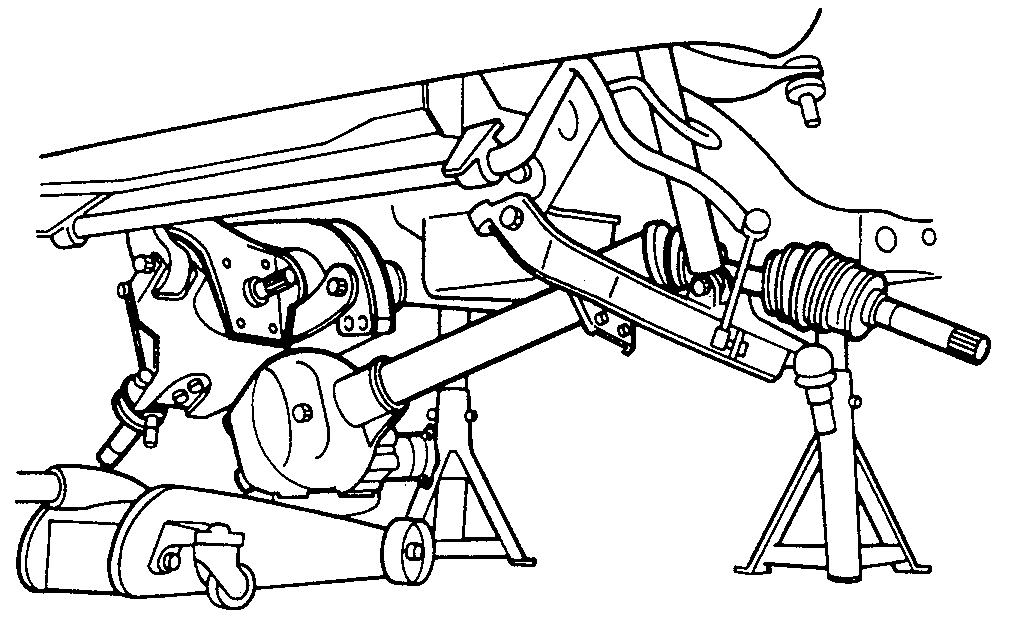
3. Suspension crossmember
4. Propeller shaft
5. Protector
6. Breather hose
- Remove the hose clip.
- Disconnect breather hose from front drive axle tube and disconnect housing.
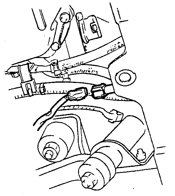
7. Vacuum hose, as follows:
a. Disconnect vacuum hose from actuator.

Pic 3

b. Shift switch connector.
- Disconnect shift switch connector.
8. Vacuum Switch Valve (VSV) assembly.

NOTE: Be sure not to remove hose and connector from VSV assembly.

Pic 4

9. Mounting bolt and nut.
10. Washer and spacer.

Pic 5

11. Bolt
- Remove the mounting bracket fixing bolt.

Pic 6

12. Front axle case assembly and front drive shaft assembly Left Hand (LH side). Lower the vehicle and disconnect the Right Hand (RH) front drive shaft assembly, and then remove the front axle case assembly and front drive shaft assembly (LH).
13. Front drive shaft assembly (RH).

ASSEMBLY
1. Front drive shaft assembly Right Hand (RH) (13)
- Lay the assembly on the lower arm.
2. Front axle case assembly and front drive shaft assembly Left Hand (LH) (12).
- Place the axle case on the jack, connect to the front drive shaft assembly (RH) before installing to the vehicle.
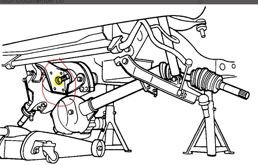
3. Bolt (11)
- Tighten the mounting bracket fixing bolt to the specified torque.
Torque: 116 Nm (85 ft. Lbs.).

Pic 7

4. Washer and spacer (10)
5. Mounting bolt and nut (9)
- Tighten the mounting bolt and nut to the specified torque.
Torque: 152 Nm (112 ft. Lbs.).
6. Vacuum Switch Valve (VSV) assembly (8)
- Tighten nuts to specified torque.
Torque: 8 Nm (69 inch lbs.).
7. Shift switch connector, as follows:
a. Install the shift switch connector.

NOTE: Be careful not to permit the entry of dust into the connector.

B. Vacuum hose. Install the actuator side of hose.

NOTE: Be careful not to permit the entry of dust into the hose.

8. Breather hose (6)
- Install the hose clip.
9. Protector (5)
- Tighten bolts to specified torque.
Torque: 26 Nm (20 ft. Lbs.).
10. Propeller shaft (4)
11. Suspension crossmember (3)
12. Steering link and arm assembly (2)
13. Hub assembly (Disc, back plate and knuckle) (1).

____________________________-

Let me know if this helps.

Joe
Was this
answer
helpful?
Yes
No
Monday, May 6th, 2019 AT 6:46 PM
Tiny
DUWHOP31
  • MEMBER
  • 151 POSTS
I have the wheel, hub, bearings, brake pads, rotor, and the backing or protection removed. I am at the knuckle. Do you know what size the vehicle speed sensor bolt is? And do I just undo it and let it hang?Also don't I need to now disconnect the upper and lower ball joint (by renting some tools from AutoZone)? And the sixth picture and seventh picture look the same to me.
Was this
answer
helpful?
Yes
No
Thursday, May 30th, 2019 AT 8:55 AM
Tiny
JACOBANDNICKOLAS
  • MECHANIC
  • 108,328 POSTS
Welcome back:

As far s the speed sensor, I believe it is a 10mm. Please understand, that is from memory and I'm hoping it's correct. It isn't something I can look up in a manual. As far as the two pictures, that is how they are listed in the manual, so rather than confusing you, I add both and indicate what pictures the directions refer to.

Now for the ball joints. The upper is bolted in and you will need a separator to take it apart from the knuckle. However, you will not need to unbolt the three retaining bolts from the control arm. You simply will need to remove the cotter pin, remove the castle nut from the ball joint, and then separate the two. I have the directions. They show a specific puller being used. You can ask at the parts store for that, or I always use what is called a fork.

___________________________________________

Here are the directions for the upper. The attached pictures correlate with the directions.

__________________________________________

UPPER

pic 1

REMOVAL
1. Raise the vehicle and support the frame with suitable
2. Remove the speed sensor from the knuckle.

Pic 2

3. Remove upper ball joint nut and cotter pin, then use remover J-36831 to remove the upper ball joint from the knuckle.

CAUTION: Be careful not to break the ball joint boot.

4. Remove bolt and washer.
5. Remove upper ball joint.

INSPECTION AND REPAIR
Make necessary parts replacement if wear, damage, corrosion or any other abnormal conditions are found through inspection.

Pic 3

- Inspect the lower end boot for damage or grease leak. Move the ball joint as shown in the figure to confirm its normal movement.
- Inspect screw/taper area of ball for damage.
- If any defects are found by the above inspections, replace the ball joint assembly with now and

pic 4

- After moving the ball joint 4 or 5 times, attach nut then measure the preload.

Starting torque: 0.5 - 3.2 Nm (0.4 - 2.4 ft. Lbs.)

If the above limits specified are exceeded, replace the ball joint assembly.

INSTALLATION
1. Install upper ball joint.
2. Install bolt and nut, then tighten them to the specified torque.

Torque: 57 Nm (42 ft. Lbs.)

3. Install nut and cotter pin, then tighten the nut to the specified torque with just enough additional torque to align cotter pin holes. Install new cotter pin.

______________________________________

The same applies to the lower. See picture 5. It shows how it comes apart.

Let me know if you have questions.

Take care,
Joe
Was this
answer
helpful?
Yes
No
Thursday, May 30th, 2019 AT 7:34 PM
Tiny
DUWHOP31
  • MEMBER
  • 151 POSTS
Thank you. So after I get the upper and lower ball joint off what are the next steps to remove the front right axle?
Was this
answer
helpful?
Yes
No
Thursday, June 27th, 2019 AT 12:11 PM
Tiny
JACOBANDNICKOLAS
  • MECHANIC
  • 108,328 POSTS
Do you have the spindle removed? If you look at the attached pic, I circled the support plate (4 bolts) and there is a snap ring that holds the axle on the inner side of that plate. I circled the plate and highlighted where the snap ring is located.

Let me know if that is what you needed.

Joe
Was this
answer
helpful?
Yes
No
Thursday, June 27th, 2019 AT 4:14 PM
Tiny
DUWHOP31
  • MEMBER
  • 151 POSTS
Do you have to remove the upper and lower ball joint first?
Was this
answer
helpful?
Yes
No
Thursday, July 4th, 2019 AT 11:15 AM
Tiny
JACOBANDNICKOLAS
  • MECHANIC
  • 108,328 POSTS
Welcome back:

The ball joints should be out. Do you have the spindle removed?

Joe
Was this
answer
helpful?
Yes
No
Thursday, July 4th, 2019 AT 6:10 PM

Please login or register to post a reply.

Sponsored links