Hello
Before I forget, not sure if you know but you don't have to drive the vehicle to AZ for them to check the codes. You can use their tool check out program and get the code scanner.
Check this out
https://www.2carpros.com/articles/car-heater-not-working
Okay, got that out of my head.........
You already checked the heater core hoses and both are the same hot temp going in and out. From what I see you have two systems.
I hate having to get a tool for something dumb........remember when radios were held in with 4 small bolts or screws! That always worked just fine.
Okay, I am going to give you information overload here since I am not sure what info your manual has. Then I will go back and review the manual, diagrams etc more in-depth and look at the TSBs as well but wanted to get this to you since you were already tearing into it.
First and biggest............I did find this in our manuals...........Also please read all as I was going through our info I would find more tips etc.........so please read all first.
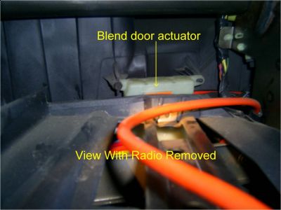
ELECTRIC BLEND DOOR ACTUATOR
Electric blend door actuator, located behind right side of dash, controls positioning of air temperature control door in response to signals from temperature control potentiometer.
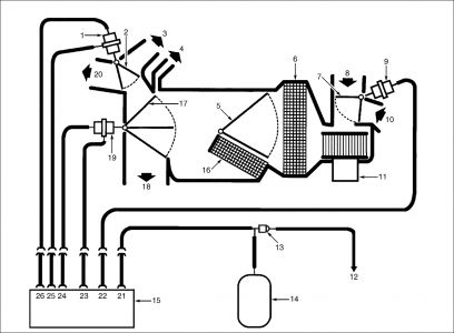
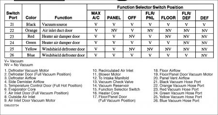
VACUUM CONTROL MOTORS
Main vacuum control motors are located on evaporator case. A single-diaphragm, 2 position, vacuum control motor is used for air inlet door. With vacuum applied, motor shaft is fully retracted and with vacuum not applied, motor shaft is fully extended.
Dual-diaphragm, 3 position, vacuum control motors are used for windshield defrost door and heater air damper door. With vacuum not applied, motor shaft is fully extended, with vacuum applied to one port, motor shaft is at center position and with vacuum applied to both ports, motor shaft is fully retracted.
Auxiliary vacuum control motor is located on evaporator case. A single-diaphragm, 2 position, vacuum control motor is used for air outlet door. With vacuum applied, airflow will be directed through A/C evaporator and out belt line and overhead register. With vacuum not applied, airflow will be directed through heater core and out rear seat airflow duct.
Here is a test concerning insufficient, erratic or no heat..............
TEST E: INSUFFICIENT, ERRATIC OR NO HEAT
1. Check For Proper Engine Coolant Level
Check engine coolant level hot and cold. If coolant is at proper level, go to next step. If coolant level is incorrect, go to step 3) .
2. Check For Hot Coolant To Heater Core Inlet
Start and run engine to normal operating temperature. Set control to full heat. Feel heater core inlet hose. If heater inlet hose is hot, go to step 4) . If hose is not hot, check cooling system and hoses. Repair as needed. Retest system.
3. Check Coolant System For Leaks
Ensure cooling system is filled to specified level. Perform cooling system pressure check. If system holds pressure, go to next step. If system does not hold pressure, repair system as needed. Retest system.
4. Check Heater Core Outlet Hose For Hot Water
With engine at normal operating temperature, set control to full heat. Feel heater core outlet hose. If heater core outlet hose is cool, repair heater core for plugged condition. If outlet hose is hot, test electronic blend door actuator. Go to TEST F .
You have done this so here is test F I gave it but you need a tester and to me I would focus on the blend door itself as the above.
TEST F: A/C DOES NOT OPERATE OR DOES NOT OPERATE CORRECTLY
1. Retrieve DTCs
Check for DTCs. See PRELIMINARY INSPECTION . If DTC B2175 is present, go to step 24) . If DTC B2175 is not present, go to next step
2. Check IC PID AC_DMD
Turn ignition off. Using New Generation Star Tester (007-00500), perform Instrument Cluster Parameter Identification A/C Demand (IC PID AC_DMD) input test. Turn ignition to run (engine off). Place function selector switch in MAX A/C position. If IC PID AC_DMD reads ON, go to step 8) . If IC PID AC_DMD is not on, go to next step.
3. Check For Short To Battery Power
Turn ignition off. Disconnect instrument cluster harness connector. Turn ignition to run (engine off). Place A/C-heater control panel function selector switch in off position. Using voltmeter, measure voltage between ground and instrument cluster harness connector Gray/Red wire terminal. Measure voltage between ground and instrument cluster harness connector Pink/White wire terminal. If voltages are more than 10 volts, repair faulty circuit(s) for short to battery. If voltage is less than 10 volts, go to next step.
4. Check Function Selector Switch For Short To Battery
Place function selector switch in ON position. Measure voltage between ground and instrument cluster harness connector Gray/Red wire terminal. If voltage is present, replace function selector switch. Retest system. If no voltage is present, go to next step.
5. Check Function Selector Switch In MAX Position
Place function selector switch in MAX A/C position. Using ohmmeter, measure resistance between instrument cluster harness connector Pink/White wire and Gray/Red wire terminals. If resistance is less than 5 ohms, replace instrument cluster module. Retest system. If resistance is more than 5 ohms, go to next step.
6. Check Pink/White Wire For Open
Disconnect function selector switch harness connector. Measure resistance of Gray/Red wire between instrument cluster and function selector switch. If resistance is less than 5 ohms, go to next step. If resistance is more than 5 ohms, repair open in Gray/Red wire. Retest system.
7. Check Pink/White Wire For Open
Measure resistance of Pink/White wire between instrument cluster and function selector switch. If resistance is less than 5 ohms, replace function selector switch. If resistance is more than 5 ohms, repair Pink/White wire. Retest system.
8. Check PCM PID WACF (With A/C Off)
Ensure air temperature is 50 °F (10 °C) or above. Turn ignition to run (engine off). Place function selector switch in off position. Using New Generation Star Tester (007-00500), perform PCM Parameter Identification Wide Open Throttle Cut-Off (PID WACF) test. If PCM PID WACF reads YES, see appropriate SELF-DIAGNOSTICS article in ENGINE PERFORMANCE. If PCM PID WACF does not read YES, go to next step.
9. Check PCM PID WACF (With A/C On)
Start and idle engine. Place function selector switch in MAX A/C position. Using New Generation Star Tester (007-00500), perform PCM PID WACF test. If PCM PID WACF reads YES, see appropriate SELF-DIAGNOSTICS article in ENGINE PERFORMANCE. If PCM PID WACF does not read YES, go to next step.
10. Check PCM PID ACCS (With A/C On)
Start and idle engine. Place function selector switch in MAX A/C position. Using New Generation Star Tester (007-00500), perform PCM Parameter Identification A/C Cycling Switch (PID ACCS) input. If PCM PID ACCS reads ON, go to step 18) . If PCM PID ACCS does not read ON, go to next step.
11. Check Refrigerant System Pressure
Turn engine off. connect A/C manifold gauge set to service ports and measure system pressure. If pressure is between 50-250 psi (3.5-17.5 kg/cm2 ), replace A/C cycling switch. If pressure is not as specified, check system for refrigerant leaks.
12. Check Fuse
Check resistance of fuse No. 7 (10-amp) in instrument panel fuse block. If fuse is okay, go to step 15) . If fuse is blown, go to next step.
13. Recheck Fuse
Turn ignition off. Install new fuse. Disconnect blend door actuator harness connector. Turn ignition to run (engine off). If fuse blows, go to next step. If fuse is okay, replace blend door actuator. Retest system.
14. Check Red/Black Circuit For Short To Ground
Disconnect A/C cycling switch. Measure resistance between ground and A/C cycling switch harness connector Red/Black wire terminal. If resistance is less than 10,000 ohms, repair short to ground in Red/Black wire. If resistance is more than 10,000 ohms, repair short to ground in Black/Yellow wire. Retest system.
15. Check Voltage At A/C Cycling Switch
Turn ignition off. Disconnect A/C cycling switch. Turn ignition to run (engine off). Place function selector switch in MAX A/C position. Measure voltage between ground and A/C cycling switch harness connector Red/Black wire terminal. If voltage is more than 10 volts, go to next step. If voltage is less than 10 volts, repair Red/Black wire. Retest system.
16. Check A/C Cycling Switch
Using New Generation Star Tester (007-00500), perform PCM PID ACCS input. Install a 5-amp fused jumper wire between A/C cycling switch harness connector Red/Black wire terminal and ground. Place function selector switch in MAX A/C position. If PCM PID ACCS reads ON, replace cycling switch. Retest system. If PCM PID ACCS does not read ON, repair Red/Black wire. Retest system.
17. Check Black/Yellow Wire For Open
Turn ignition off. Connect Breakout Box (014-00950) to PCM connector C103. DO NOT connect breakout box to PCM. Measure resistance between breakout box pin No. 41 and A/C cycling switch harness connector Black/Yellow wire terminal. If resistance is less than 5 ohms, replace PCM. Retest system. If resistance is more than 5 ohms, repair Black/Yellow wire. Retest system.
18. Check PCM PID WAC (With A/C On)
Place function selector switch in MAX A/C position. Using New Generation Star Tester (007-00500), perform PCM PID WAC. If PCM PID WAC reads ON, go to next step. If PCM PID WAC does not read on, see appropriate SELF-DIAGNOSTICS article in ENGINE PERFORMANCE.
19. Check Orange Wire For Open
Turn ignition off. Disconnect A/C clutch relay harness connector (located in engine compartment junction box). Turn ignition to run (engine off). Measure voltage between A/C clutch relay connector Orange wire terminal and ground. If voltage is more than 10 volts, go to next step. If voltage is less than 10 volts, repair Orange wire. Retest system.
20. Check A/C Clutch Relay
Turn ignition off. Reconnect A/C clutch relay connector. Disconnect A/C clutch harness connector. Turn ignition to run (engine off). Place New Generation Star Tester (007-00500) in ACTIVE COMMAND MODE and command PCM outputs ON. Measure voltage between A/C clutch harness connector Pink/Light Blue wire terminal and ground. If voltage is more than 10 volts, go to next step. If voltage is less than 10 volts, go to step 22) .
21. Check Black Wire For Open
Turn ignition off. Measure resistance between A/C clutch harness connector Black wire terminal and ground. If resistance is less than 5 ohms, replace A/C clutch. Retest system. If resistance is more than 5 ohms, repair Black wire. Retest system.
22. Check Pink/Light Blue Wire For Open
Turn ignition off. Disconnect A/C clutch relay harness connector. Disconnect A/C diode harness connector (located in engine compartment junction box). Measure resistance of Pink/Light Blue wire between A/C clutch relay harness connector and A/C diode harness connector. If resistance is less than 5 ohms, go to next step. If resistance is more than 5 ohms, repair Pink/Light Blue wire. Retest system.
23. Check Circuit From Diode To
A/C Clutch
Measure resistance of Pink/Light Blue wire between A/c diode harness connector and A/C clutch harness connector. If resistance is less than 5 ohms, replace A/C clutch relay. Retest system. If resistance is more than 5 ohms, repair open in Pink/Light Blue wire. Retest system.
24. Check Function Selector Switch Circuit For Short To Ground
Turn ignition off. Disconnect instrument cluster 20-pin (C240) and 22-pin (C241) harness connectors. Place function selector switch in MAX A/C position. Measure resistance between instrument cluster C241 harness connector Gray/Red wire terminal and ground. If resistance is more than 10,000 ohms, go to next step. If resistance is less than 10,000 ohms, go to step 26) .
25. Check Tan/Black Wire For Short
Disconnect function selector switch harness connector (C244). Measure resistance between ground and instrument cluster harness connector (C240) Tan/Black wire terminal. If resistance is more than 10,000 ohms, replace instrument cluster. If resistance is less than 10,000 ohms, repair Tan/Black wire. Retest system.
26. Check Gray/Red Wire For Short
Disconnect function selector switch harness connector (C247). Measure resistance between instrument cluster C241 harness connector Gray/Red wire terminal and ground. If resistance is more than 10,000 ohms, go to next step. If resistance is less than 10,000 ohms, repair Gray/Red wire. Retest system.
27. Check Pink/White Wire For Short
Measure resistance between instrument cluster C240 harness connector Pink/White wire terminal and ground. If resistance is more than 10,000 ohms, replace function selector switch. Retest system. If resistance is less than 10,000 ohms, repair short in Pink/White wire.
Retest system.
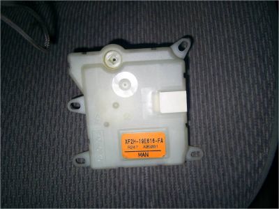
BLEND DOOR ACTUATOR
Removal & Installation
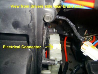
Remove radio. Remove left side instrument panel isolator. Disconnect electrical connector. Remove 3 actuator attaching screws. Pull down to release actuator shaft and remove actuator. To install, reverse removal procedure. Make sure door shaft is completely in and properly seated.
Tip: Blend Door Actuator Removal
Current rating is 3.4 (rated by 16 shops)
Click to rate tip.
Showing 1-4 of 4
Posted By: Tim__G Flag Post For Monitor Review
Shop: JAYS CAR REPAIR
Date: 2/1/2008 8:58:36 PM
Had 2 Windstars this week with broken Blend door actuator.
Concern:
No hot air from HVAC. Clicking noise from dash area. Fan Speeds work normal.
Suspect:
Electric blend door actuator, Common problem that many techs have seen before.
Repair:
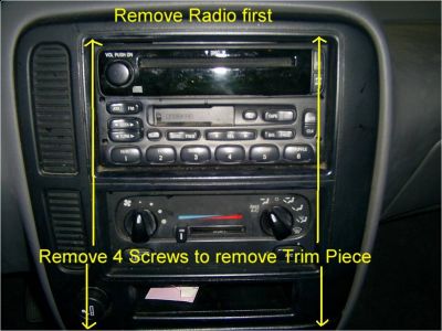
Remove radio ( special U shaped tool required Part # Unknown) Or other techs have used metal shirt hangers.
Remove radio and A/C Heater Control head. (4 screws 2 at top of radio 2 at either side of ashtray)
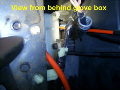
If van has aftermarket radio and you can not get the radio out easily, you can remove by swinging down glove box and removing 1 screw there and the 2 others screws from drives side brake and gas pedal area.
See attached pictures.
Remove 3 screws securing Blend door actuator.
General Info...........
The A/C-heater system is a fixed orifice tube, cycling clutch type with a suction accumulator-drier, and a plate/fin-type evaporator core. A fixed orifice tube, a dual-function pressure cut-off switch, and an A/C clutch cycling switch control system operation.
High pressure relief valve provides system protection. Pressure in excess of 450 psi (31.6 kg/cm2 ) will cause pressure relief valve to vent refrigerant to atmosphere. High pressure relief valve will close when pressure is less than 450 psi (31.6 kg/cm2 ).
Auxiliary A/C-heating system, if equipped, uses an expansion valve to meter refrigerant flow to auxiliary evaporator. Auxiliary system is interconnected to main A/C-heater system for refrigerant flow and heat exchange through condenser. Auxiliary system includes a separate evaporator, an independently adjustable blower motor, heater core, vacuum control for air door, and ducting.
OPERATION
MAIN A/C-HEATER SYSTEM
System airflow is controlled by a 6-port vacuum selector valve, an integral part of control panel. System air temperature is manually controlled by temperature control switch, which controls electric-actuated temperature blend-air door.
Blower motor electrical circuit uses ground side switching with blower switch and resistor assembly on ground side of motor, not battery side. This protects resistor assembly from overheating in the event of an electrical short.
During system operation, with function selector switch in any setting except off and MAX A/C positions, blower motor and wheel draw air directly into system through cowl air intake. In MAX A/C position, air flows from inside vehicle through recirculation duct. Once in system, air is blower driven through evaporator core and, depending on setting of temperature control switch, through and/or around heater core and into plenum. Air is directed from plenum to defrost nozzles, floor and instrument panel registers, depending on position of function selector switch.
AUXILIARY A/C-HEATER SYSTEM
Auxiliary A/C-heater system, if equipped, is controlled by main A/C-heater system. Auxiliary system is equipped with 2 blower control switches (front and rear-mounted). If front auxiliary blower control switch is set to "0" (off) position, auxiliary A/C-heater system will be off.
If front auxiliary blower control switch is set to any fan speed, air will be discharged from rear vents at the corresponding speed. When front auxiliary switch is in REAR CTRL position, fan speed can be controlled from rear auxiliary blower control switch.
CONTROL PANELS
Function Selector Switch
The function selector switch actuates a 6-port vacuum selector, which controls air source intake and air distribution within system. The function selector switch also controls blower on-off switch and A/C compressor clutch operating circuit. The following function selector switch settings affect air distribution:
MAX A/C
The A/C-heater air inlet door is closed to outside air. Air from passenger compartment is drawn through recirculation opening and blown across evaporator core, past closed doors to floor and defrost outlets, and out through the dash panel. Air blown across evaporator core can be diverted across heater core, using temperature control switch, to warm air. A/C compressor and blower motor will both be operating when MAX A/C is selected.
Normal A/C
Airflow follows same course as in MAX A/C mode, except A/C-heater air inlet duct door is set to draw outside air instead of recirculated air. A/C compressor and blower motor will both be operating when normal A/C is selected.
Floor
Outside air is drawn into system, blown past evaporator core and through heater core. Windshield defrost door is in vacuum position, and heater air damper door is in no vacuum position. Airflow is directed mostly to floor outlets, with a small amount going to the windshield and side vents. Blower motor is operating.
Vent
With function selector switch in vent position, outside air is drawn into system and blown past evaporator core. Depending on blend-air door setting, air then by-passes heater core and is directed past vacuum-closed heater air damper door. Air temperature can be heated to more than, but not cooled to less than outside air temperature. In vent position, windshield defrost door is closed by vacuum to defrost outlet, and air flows through panel outlet and ducts to instrument panel registers. Blower motor is operating.
Floor/Vent
With function selector switch in floor/vent position, outside air is drawn into system, past evaporator core. The temperature blend-air door setting determines amount of input air heated by heater core and allowed to by-pass heater core.
The heater air damper door receives partial vacuum. As a result, this door opens halfway to allow airflow to floor and vent. The windshield defrost door is at full vacuum, closing off airflow to defrost outlets. Blower motor is operating.
Defrost/Floor
With function selector switch in defrost/floor position, outside air is drawn into system, past evaporator core. The temperature blend-air door setting determines amount of input air heated by heater core and allowed to by-pass heater core.
The windshield defrost door is in the middle position (vacuum to rear port), allowing airflow to windshield and floor outlets, with a small amount going to the side outlets. The heater air damper door is at full vacuum, closing off airflow to dash vents. A/C compressor is operating to dehumidify air and reduce windshield fogging.
Defrost
With function selector switch is turned to defrost symbol, vacuum to system is cut off. Temperature blend-air door determines amount of input air heated by heater core and allowed to by-pass heater core.
Heater air damper door is at full vacuum, blocking airflow to dash vents. Windshield defrost door is in the no vacuum position, directing most incoming air to defrost outlets, with a small amount going to floor and side vent outlets. A/C compressor will operate if outside temperature is more than 45-50 °F (5-10 °C), dehumidifying incoming air to reduce windshield fogging.
Temperature Control Switch
Temperature is controlled by electric-actuated blend-air door, located on evaporator case. The blend-air door can be closed or opened, allowing cooled or heated outside air to be discharged from outlets.
Main Blower Switch
Blower speeds are controlled by blower switch and resistor assembly. There are 4 fan speed settings: low speed, 2 intermediate speeds, and high speed. Fan is turned off when function selector switch is in "0" (off) position.
Auxiliary Blower Switches
Fan speeds for rear passenger compartment is controlled by front and rear auxiliary blower switches. See Fig. 1 and Fig. 2 . If front switch (on front control panel) is set to "0" (off) position, auxiliary A/C-heater system will be off. If front switch is set to any fan speed position (1, 2 or 3), air will be discharged from rear vents at corresponding speed. If front switch is in REAR CTRL position, fan speed can be controlled from rear auxiliary blower switch (on rear passenger compartment control panel). Rear blower switch has 4 different speed settings.
Dec 20, 2009 at 11:39 AM