Installation Without Key (Bronco, "E" & "F" Series With Non-Tilt Steering)
NOTE:Retain ignition switch actuating rod from removed casting assembly for use with NEW flange casting assembly.
Replace removed assembly with NEW assembly consisting of the following:
Flange casting assembly.
Lock cylinder assembly.
Lock gear (steering column lock).
Bearing (steering column lock).
Retainer (steering column upper bearing).
Actuator assembly (steering column lock).
Lubricate ignition lock cylinder with grease. Install key release lever assembly on M/T equipped vehicles or "PRND2 1" insert on A/T equipped vehicles. Install "T" bolts and lock actuator insert. Reassemble NEW assembly parts. Install NEW upper shaft bearing and set actuator to drive gear. To complete installation, reverse removal procedure. Using ignition key, rotate ignition lock cylinder to ensure correct mechanical operation in all positions.
Removal Without Key (Bronco, "E" & "F" Series With Tilt Steering)
NOTE:This procedure is used for removing ignition lock cylinder when key is missing or cylinder is frozen.
Disconnect negative battery cable. Remove steering column trim shrouds. Tape gap between steering wheel hub and cover casting. Pull out hazard flasher switch and tape it down toward vehicle floor to provide clearance for drilling out lock cylinder retainer pin.
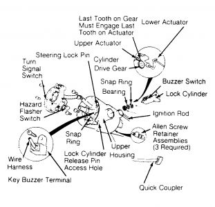
Tilt column lock cylinder retaining pin is located on outside of steering column cover casting, adjacent to hazard flasher button. See Fig. 4 . Tilt steering column to full up position and pre-punch lock cylinder retaining pin with center punch.
CAUTION:When drilling out retaining pin, take care not to damage cover cast housing or hazard flasher switch.
Using a right angle drill and a 1/8" (3.17 mm) drill bit, drill out the retaining pin. DO NOT drill deeper than 1/2" (12.7 mm). Tilt steering column to full down position. Place a chisel at base of ignition lock cylinder cap. Using a hammer, strike chisel with sharp blows to break cap away from ignition lock cylinder.
Using a 3/8" (9.8 mm) drill bit, drill down middle of ignition lock key slot approximately 1-3/4" (45 mm) until lock cylinder breaks loose from steering column cover casting. Remove ignition lock cylinder. Remove drill shavings from base of cover cast housing.
Remove steering wheel and pad. Remove turn signal lever from column and then remove 2 screws from turn signal switch. Remove one screw from key warning buzzer terminal. Lift turn signal switch up and over end of steering shaft but do not disconnect it from wiring harness.
NOTE:Removal of cover casting will expose upper actuator.
Remove 4 screws from cover casting and lift casting over end of steering shaft, allowing turn signal switch to pass through cover casting. Remove upper actuator. Remove drive gear, snap ring, washer and upper actuator from cover casting. Ensure all components are cleaned and free of drill shavings.
Installation Without Key (Bronco, "E" & "F" Series With Tilt Steering)
Lubricate tang of lock cylinder with grease. Attach upper actuator to lower actuator and lubricate upper actuator. Reassemble cover casting. To complete installation, reverse removal procedure. Using ignition key, rotate ignition lock cylinder to ensure correct mechanical operation in all positions. Ensure that START circuit cannot be actuated in Drive or Reverse positions.
Removal (Bronco II & Ranger)
Disconnect negative battery cable. Remove trim shroud. Remove electrical connector from key warning switch. Turn ignition switch to "RUN" position.
Place a 1/8" diameter pin in the hole located in outer edge of lock cylinder housing. Depress retaining pin and pull out lock cylinder.
Installation (Aerostar, Bronco, "E" & "F" Series)
With lock cylinder and switch in "LOCK" position, engage actuator rod in switch. Position switch on column and install retaining nuts, but do not tighten. Move switch up and down along column to locate mid-position of rod lash, and tighten retaining nuts.
Fig. 4: Exploded View of Tilt Steering Column & Switch Assemblies (Bronco, "E" & "F" Series)
Courtesy of FORD MOTOR CO.
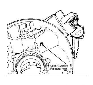
Fig. 5: Ignition Lock Cylinder Release Pin - Non-Tilt (Bronco, "E" & "F" Series)
Courtesy of FORD MOTOR CO.
Dec 11, 2008 at 2:09 PM
