1996 Ford Taurus Cruise control and horn not working

Tiny
1940PLYM
  • MEMBER
  • 1996 FORD TAURUS
  • 6 CYL
  • FWD
  • AUTOMATIC
  • 91,300 MILES
Hello:
I have the above mentioned vehicle. Approximately 2 weeks ago the horn and cruise control stopped working. When the cruise control "ON" button on the steering wheel is pressen, nothing happens including the cruise light on the dash not coming on. The brake lights work and everything else works as far as I know. I read on this and other website that several people had the same problem and many times it was mentioned the clockspring was the problem. I purchased a new clockspring and installed it but this did not fix the problem. I also checked the fuses and all checked OK with an Ohm meter.
Any assistance would be greatly appreciated.
Thanks so much.
Sincerely,
Carl Sinner
Saturday, September 5th, 2009 AT 11:55 AM

18 Replies

Tiny
MERLIN2021
  • MECHANIC
  • 17,250 POSTS
TESTING SYSTEM INOPERATIVE 1. Check Power To Servo - Unplug harness connector from servo. Turn ignition on. Using DVOM, measure voltage between pins No. 7 and 10 of servo connector. See Fig. 1 . If battery voltage exists, go to step 4). If battery voltage does not exist, go to next step. 2. Check Power To Servo - Turn ignition on. Check for battery voltage between servo connector pin No. 7 and chassis ground. If battery voltage exists, go to next step. If battery voltage does not exist, check fuses and replace as necessary. If fuses are okay, repair open power circuit. If fuse repeatedly blows check circuit for short to ground and repair as necessary. 3. Check Module Ground - Measure resistance between servo connector pin No. 10 and chassis ground. If resistance is less than 5 ohms, repeat step 1). If resistance is greater than 5 ohms, repair ground circuit. 4. Check Deactivator Switch Circuit - Turn ignition on. With brake released, measure voltage between pin No. 9 at servo connector and ground. If battery voltage exists, go to step 7). If battery voltage does not exist, go to next step. 5. Check Power To Deactivator Switch - Disconnect deactivator switch harness connector. See DEACTIVATOR SWITCH LOCATION table. Check for battery voltage at deactivator switch Light Green/Red wire. If battery voltage exists, go to next step. If battery voltage does not exist, check for blown fuse or open circuit. Repair as necessary.


https://www.2carpros.com/forum/automotive_pictures/62217_Taurd_1.gif


https://www.2carpros.com/forum/automotive_pictures/62217_tuara_1.jpg


https://www.2carpros.com/forum/automotive_pictures/62217_Taurd_2.gif


https://www.2carpros.com/forum/automotive_pictures/62217_taub_1.jpg


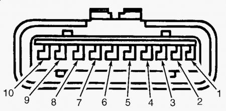
6. Check Deactivator Switch-To-Servo Circuit - Measure resistance between servo connector pin No. 9 and matching wire color at deactivator switch harness connector. If resistance is less than 5 ohms, replace deactivator switch. If resistance is greater than 5 ohms, repair open circuit between deactivator switch and servo connectors. 7. Check Stoplight Switch - With brake pedal released, measure voltage on pin No. 4 at servo connector. If battery voltage exists, replace stoplight switch. If battery voltage does not exist, go to next step. 8. Check Stoplight Circuit - Measure voltage on pin No. 4 at servo connector while depressing brake pedal. If battery voltage exists, go to step 12). If battery voltage does not exist, go to next step. 9. Check Stoplight Switch Resistance - Disconnect stoplight switch. Measure resistance across stoplight switch terminals while exercising switch. On probe, measure across terminals No. 1 and 4. If resistance is less than 5 ohms with brakes applied, go to next step. If resistance is greater than 5 ohms, with brakes applied, replace stoplight switch. 10. Check Power To Stoplight Switch - Disconnect stoplight switch harness connector. Check for battery voltage at stoplight switch Light Green/Red wire. If battery voltage exists, go to next step. If battery voltage does not exist, check for blown fuse or open circuit. Repair as necessary. 11. Check Stoplight Switch-To-Servo Circuit - Measure resistance between servo connector pin 19. Check Vehicle Speed Sensor (VSS) Circuit - Test drive vehicle. If speedometer is inoperative, diagnose and repair VSS or VSS circuit as necessary. See appropriate TESTS W/CODES article in ENGINE PERFORMANCE section. If speedometer operates okay, Disconnect harness connectors from VSS and servo. Measure resistance of wire between servo pin No. 3 and same color wire at VSS harness connector. If resistance is less than 5 ohms, go to next step. If resistance is greater than 5 ohms, repair open in VSS (servo pin No. 3) circuit. 20. Check For Broken Or Binding Servo Cable - Remove servo cable from servo. Check for broken or binding cable by pulling on cable ball slug. Replace cable as necessary. If cable is okay, replace servo. SET SPEED FLUCTUATES 1. Check Servo Cable & Throttle Linkage For Binding - Verify condition. Ensure engine is properly tuned. If condition occurs when cruise control is off, repair engine as required. If condition only occurs when cruise control is activated, check servo cable, throttle linkage, or throttle plate for binding or sticking. Repair as necessary. 2. Check Vehicle Speed Sensor - Unplug VSS connector. Measure resistance between VSS terminals. If resistance is not 200-300 ohms, replace VSS. If resistance is 200-300 ohms, check VSS circuit for open or short. If wiring is okay, go to next step. 3. Replace Servo - Substitute a known-good servo. Test drive vehicle and check for proper cruise control operation. If speed still fluctuates, check PCM for stored codes. See appropriate TESTS W/CODES article. SYSTEM DOES NOT DISENGAGE WHEN BRAKES ARE APPLIED 1. Check Deactivator Switch Circuit - Disconnect servo connector. Without brakes applied, measure voltage between servo connector pins No. 9 and 10. If battery voltage exists, go to next step. If battery voltage does not exist, repair deactivator circuit. See SYSTEM INOPERATIVE test. 2. Check Deactivator Switch Operation - Disconnect servo connector. Apply brakes. Measure voltage between servo connector pins No. 9 and 10. If battery voltage exists, replace deactivator switch. If battery voltage does not exist, go to next step. 3. Check Stoplight Switch - Unplug servo connector. With brakes applied, measure voltage between servo connector pins No. 4 and 10. See Fig. 1 . If battery voltage exists, go to next step. If battery voltage does not exist, replace brake switch, fuse, or repair open circuit. 4. Check For Binding Servo Cable - Remove servo cable from servo. Check for breaks or binding by pulling on cable ball slug. If throttle does not operate freely, check throttle plate operation. Replace cable if necessary. If cable is okay, replace servo assembly. COAST, RESUME OR OFF FUNCTION INOPERATIVE Unplug servo connector. Measure resistance between pins No. 5 and 6 of servo connector while depressing each function switch and rotating steering wheel. If all resistance readings are as specified, replace servo. See CONTROL SWITCH RESISTANCES table.
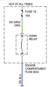
HORN Disconnect horn switch connector(s). Continuity should not exist between horn switch wires with horn button(s) released. Press horn button(s). Continuity should exist.
Was this
answer
helpful?
Yes
No
Saturday, September 5th, 2009 AT 12:11 PM
Tiny
1940PLYM
  • MEMBER
  • 10 POSTS
Thanks for your quick and informative response. One question I have refers to the part of your response where it says "See DEACTIVATOR SWITCH LOCATION table." Where is this table?
Also in #4 it says to check the deactivator SWITCH CIRCUIT.
Thanks so much again for your help.
Sincerely,
Carl Sinner
Was this
answer
helpful?
Yes
No
Saturday, September 5th, 2009 AT 3:23 PM
Tiny
MERLIN2021
  • MECHANIC
  • 17,250 POSTS
The cruise deactivator is on the brake pedal arm above the BOO(brake on off) switch. I don't know about the edmonds problem, that would be something the admins did!
Was this
answer
helpful?
Yes
No
Saturday, September 5th, 2009 AT 3:27 PM
Tiny
1940PLYM
  • MEMBER
  • 10 POSTS
Hello:
I was following the testing instructions you sent me and got to #4 where it says to measure voltage between pin 9 of the servo connector and ground. There is not a wire in position 9 or position 3 on the servo connector. I looked to be sure the wires did not come out of the connector and it appears there never were wires in positions 9 and 3. The next test I did was #7 where I checked the stoplight switch. There was battery voltage between pin #4 on the servo connector and ground which according to your instructions, indicates a bad stoplight switch. However when I press the brake pedal, the stop lights come on and when the pedal is released, the stop lights go off. Could the switch still be bad and need replaced?
All other tests through step #7 I could do, not involving pin #9 checked out OK.
Thank you.
Was this
answer
helpful?
Yes
No
Sunday, September 6th, 2009 AT 8:49 AM
Tiny
MERLIN2021
  • MECHANIC
  • 17,250 POSTS
Wiring diagram emailed to you, pin 9 shows an orange wire to the deactivator switch.
Was this
answer
helpful?
Yes
No
Sunday, September 6th, 2009 AT 10:08 AM
Tiny
MERLIN2021
  • MECHANIC
  • 17,250 POSTS
Try unplugging the deactivator, use a jumper wire accross the plug terminals, go for a test drive. Let us know. The light green/red wire on the BOO and deactivator are shared, and have the same fuse.
Was this
answer
helpful?
Yes
No
Sunday, September 6th, 2009 AT 10:10 AM
Tiny
1940PLYM
  • MEMBER
  • 10 POSTS
Hello. Well I found part of the problem. I got the servo plug turned right after I started testing and pin 1 was where pin 10 would be. Anyhow I retested what I tested already and all tested fine. Step #8 showed battery voltage and it states if there is battery voltage there go to step 12. However the next numbered steps are 9, 10, 11, and then 20. Did something not show and print on the email instructions you sent?
Thanks again so much and sorry for the problem. It was my error.
Carl
Was this
answer
helpful?
Yes
No
Sunday, September 6th, 2009 AT 3:11 PM
Tiny
MERLIN2021
  • MECHANIC
  • 17,250 POSTS
12. Check For Stuck ON Switch - With no cruise control switches pressed, check voltage on pin No. 5 at servo connector. If battery voltage exists, replace cruise control switch assembly. If battery voltage does not exist, go to next step. 13. Check ON Switch Operation - While pressing cruise control ON switch, measure voltage of pin No. 5 at servo connector. If battery voltage exists, go to step 17). If battery voltage does not exist, go to next step. 14. Check For Power To Clockspring - Disable air bag system. See AIR BAG RESTRAINT SYSTEM article. Disconnect clockspring connector at base of steering column. Turn ignition on. Check for battery voltage Yellow/Light Green wire at harness connector at base of steering column. If battery voltage exists, go to next step. If battery voltage does not exist, replace blown fuse or repair open circuit between fuse panel and clockspring connector. 15. Check Clockspring - Disable air bag system. See AIR BAG RESTRAINT SYSTEM article. Disconnect clockspring connector at base of steering column. Remove drivers-side air bag module. Remove cruise control actuator switch assembly. Measure resistance of all wires between base of steering column and actuator switch connector on clockspring. Rotating steering wheel. If resistance is greater than 0.5 ohm on any circuit, replace clockspring. If resistance is less than 0.5 ohm on all circuits, go to next step. 16. Check Circuits From Clockspring To Servo - Disconnect servo electrical connector. Measure resistance between servo terminals No. 5 and same color wire in clockspring connector (harness side) at base of steering column. See Fig. 1. Repeat procedure for servo connector terminal No. 6. If resistance is greater than 3 ohms, repair suspect wire(s). If resistance is less than 3 ohms, check circuits for short to ground and repair as necessary. If okay, go to next step. 17. Check For Stuck Switch - Disconnect servo connector. Measure resistance between terminals No. 5 and 6 at servo connector. Do not press any cruise control switches on steering wheel. If resistance is greater than 3000 ohms, go to next step. If resistance is less than 3000 ohms, replace cruise control command switch assembly. 18. Check Switch Resistance - To check switches, measure resistance between pins No. 5 and 6 of servo connector while pressing each control button. If any resistance is not as specified, replace control switch assembly. See CONTROL SWITCH RESISTANCES table. If all resistances are as specified, go to next step. CONTROL SWITCH RESISTANCES 19. Check Vehicle Speed Sensor (VSS) Circuit - Test drive vehicle. If speedometer is inoperative, diagnose and repair VSS or VSS circuit as necessary. See appropriate TESTS W/CODES article in ENGINE PERFORMANCE section. If speedometer operates okay, Disconnect harness connectors from VSS and servo. Measure resistance of wire between servo pin No. 3 and same color wire at VSS harness connector. If resistance is less than 5 ohms, go to next step. If resistance is greater than 5 ohms, repair open in VSS (servo pin No. 3) circuit. Button Depressed Ohms COAST 115-125 OFF 0-4 RESUME 2090-2310 SET/ACCEL 645-715
Aorry about the missing info, hope this helps! Did you try my suggestion yet?
Was this
answer
helpful?
Yes
No
Sunday, September 6th, 2009 AT 9:08 PM
Tiny
1940PLYM
  • MEMBER
  • 10 POSTS
Hello and thanks for the additional information. As far as trying your suggestion, I did not yet because I wanted to try the rest of the test steps first. As for the suggestion, do I jump across the plug end coming from the deactivator switch or the plug end going away from the switch ie do I jump across the female or male ends in the connector?
Thanks again and have a good holiday.
Carl
Was this
answer
helpful?
Yes
No
Monday, September 7th, 2009 AT 7:16 AM
Tiny
1940PLYM
  • MEMBER
  • 10 POSTS
Hello:
In step #14, it asks me to check for battery voltage on the yellow/light green wire on the harness connector. The connector I am checking has 4 wires, 2 black, one blue, and one yellow. There are none that are yellow/light green. When I check for voltage on each of these wires, the only one with battery voltage is the blue one. Am I checking the right connector? The other one is a 2 pin connector with a gray/white and a red/gray wires.
Thank you and thanks for all of your patience wiith this issue and with me.
Carl
Was this
answer
helpful?
Yes
No
Monday, September 7th, 2009 AT 3:35 PM
Tiny
MERLIN2021
  • MECHANIC
  • 17,250 POSTS
No other connector at the end of the steering column? When you jump the switch, unplug the connector, and jump at plug end of the harness, not the switch!
Was this
answer
helpful?
Yes
No
Tuesday, September 8th, 2009 AT 6:18 AM
Tiny
1940PLYM
  • MEMBER
  • 10 POSTS
Good morning:
There are 2 connectors at the end of the steering column. One for the BOO switch and the other for the deactivator switch. I just now disconnected the deactivator connector and used a jumper wire across the plug terminals at the plug end of the harness. I took it for a test drive and still no cruise control or horn.
I did get the wiring diagram you emailed me but as I said, the color of the 4 wires in the clockspring connector are blue, yellow and 2 black. The only one with voltage is the blue one. This connector I assume is the one from the clockspring connector since when I follow it back to the steering wheel, it connects to the clockspring. The other connector coming from the steering wheel is a 2 pin connector connected to the airbag.
Thank you.
Carl
Was this
answer
helpful?
Yes
No
Tuesday, September 8th, 2009 AT 8:02 AM
Tiny
MERLIN2021
  • MECHANIC
  • 17,250 POSTS
It shows light green in the diagram test that one also check your horn relay under the hood in the power distribution center. Relay #29.


https://www.2carpros.com/forum/automotive_pictures/62217_pdc_2.jpg

Was this
answer
helpful?
Yes
No
Tuesday, September 8th, 2009 AT 9:06 AM
Tiny
1940PLYM
  • MEMBER
  • 10 POSTS
I checked the light green wire in the 4 pin clockspring connector and there is no battery voltage with the ignition key on. There is battery voltage in a blue wire in the same connector. Also I switched the horn relay with the wiper relay and the wipers worked. When I put the wiper relay in the horn relay spot, the horn still did not work.
Thank you.
Was this
answer
helpful?
Yes
No
Tuesday, September 8th, 2009 AT 11:04 AM
Tiny
MERLIN2021
  • MECHANIC
  • 17,250 POSTS
Test for power at the relay socket And check fuse #19 in the power distribution center.


https://www.2carpros.com/forum/automotive_pictures/62217_taur_2.jpg

Was this
answer
helpful?
Yes
No
Tuesday, September 8th, 2009 AT 3:46 PM
Tiny
1940PLYM
  • MEMBER
  • 10 POSTS
In the power distribution box under the hood, fuse #19 is a 30A fuse and controls the headlights. Fuse #22 which is a 15A fuse is marked horn in the owners manual. The 15A horn fuse is good and there is power on one leg where the fuse plugs in. As for the horn relay, when standing in front of the car and looking down at the horn relay socket, there are 3 receptacles closest to the front of the car, one just above these three and one more above this one. The one farthest from the front of the car and the left one of the botton three have battery power at all times. If I use a jumper wire between either one of these hot receptacles and the middle receptacle, the horn blows.
Thank you.
Was this
answer
helpful?
Yes
No
Wednesday, September 9th, 2009 AT 8:02 AM
Tiny
MERLIN2021
  • MECHANIC
  • 17,250 POSTS
Then either the relay or the switch on steering wheel are no good, or the clockspring you got was defective? Horn needs to work for cruise to work! Take clockspring back and see if they will give you a new one.
Was this
answer
helpful?
Yes
No
Thursday, September 10th, 2009 AT 2:33 AM
Tiny
1940PLYM
  • MEMBER
  • 10 POSTS
I am assuming the relay is OK since the horn relay works when used in the washer pump or the wiper sockets. As for the switch on the steering wheel, I assume you refer to the CRUISE ON switch and I feel pretty confident that is OK too.
Thnks so much for all of your help over the past several days. I really appreciate it. I will also be recommending your web site to anyone needing help with any aotomotive problems. Thanks again and have a good week.
Sincerely,
Carl Sinner
Was this
answer
helpful?
Yes
No
Thursday, September 10th, 2009 AT 6:35 AM

Please login or register to post a reply.

Sponsored links